1. Affinity Law and Energy Saving Potential
The centrifugal pump power law states that pump shaft power is proportional to the cube of pump speed: P₂ = P₁ × (n₂/n₁)³. This cubic relationship between speed and power is the foundation of the economic case for VFD speed control on centrifugal pump drives. Even modest speed reductions produce large power savings because the saving is amplified cubically.
| Speed Reduction | % of Full Speed | Power as % of Full Speed | Power Saving | Flow Reduction |
|---|---|---|---|---|
| −5% | 95% | 85.7% | 14.3% | 5% |
| −10% | 90% | 72.9% | 27.1% | 10% |
| −20% | 80% | 51.2% | 48.8% ↑ | 20% |
| −30% | 70% | 34.3% | 65.7% | 30% |
| −40% | 60% | 21.6% | 78.4% | 40% |
Throttling the pump discharge valve to reduce flow does not proportionally reduce the power consumed by the motor. When the valve is partially closed, the pump operates at a higher head point on its curve, which is less efficient than its best efficiency point. The motor continues to consume close to full power while most of that energy is wasted as heat across the valve restriction rather than useful hydraulic work. VFD speed control eliminates this waste: the pump produces exactly the flow required, at the correct head, at the optimal efficiency point on the pump curve for that duty condition.
2. Why Standard Motors Fail on Pump VFD Drives
A pump fitted with a VFD frequently operates at 40 to 80% of rated speed during off-peak demand periods. At these reduced speeds, a standard IC411 motor’s shaft-mounted fan produces only 6 to 51% of full-speed cooling airflow, while the motor must still produce sufficient torque to overcome pump friction and maintain flow against the system head. The reduced cooling combined with continued torque production causes the winding temperature to exceed the Class F limit, accelerating insulation ageing and leading to premature motor failure within 2 to 5 years on a duty that the pump system was designed to serve for 20 or more years.
Modern IGBT-based VFDs switch at 2 to 16 kHz, generating voltage spikes of 1,000 to 1,600 V at the motor terminals (amplified by cable length reflection effects). Standard Class F motor winding insulation is rated for sinusoidal voltage waveforms — the repeated high-frequency voltage spikes cause partial discharge within the winding insulation and progressive insulation breakdown. This failure mode is entirely absent when the motor operates on a fixed-frequency sinusoidal supply, but becomes the primary failure mechanism when a standard motor is connected to a VFD without adequate insulation specification.
VFD common-mode voltage induces shaft currents that discharge through motor bearings, causing EDM (electrical discharge machining) of the bearing races. This produces characteristic frosting and fluting on the bearing race surface, increased vibration, and bearing failure within 6 to 24 months. Pump motors on VFDs without bearing current protection (insulated NDE bearing or shaft grounding ring) fail from bearing damage before the insulation failure mode has time to progress. Both failure mechanisms must be addressed simultaneously in the YVF2 motor specification for pump VFD drives.
3. YVF2 IC416 Cooling at Low Pump Speed
The Korea Ever-Power YVF2 series uses IC416 forced cooling — a separate independently powered blower motor mounted on the non-drive end provides a constant cooling airflow across the motor frame regardless of the main motor shaft speed. When the VFD reduces the pump motor speed to 50% (25 Hz) for low-demand operation, the IC416 blower continues to provide 100% of rated cooling airflow, allowing the YVF2 to produce full rated torque at this reduced speed without any thermal derating.
The IC416 blower is powered from the main three-phase supply (not from the VFD output), ensuring it runs at full rated speed regardless of VFD frequency. The blower motor is typically 1/20 to 1/10 the rated power of the main motor — for a 22 kW YVF2, the blower is approximately 0.18 to 0.37 kW — and its power consumption is negligible compared to the energy saving from VFD speed control on the main pump drive.
| Speed | IC411 Cooling | IC416 Cooling |
|---|---|---|
| 50 Hz (100%) | 100% | 100% |
| 40 Hz (80%) | 51% | 100% |
| 25 Hz (50%) | 12.5% | 100% |
| 15 Hz (30%) | 2.7% | 100% |
| 0 Hz (static) | 0% | 100% |
4. Worked Energy Saving Calculation — 22 kW Pump
Motor efficiency (IE3): 92.6%
Annual operating hours: 8,000 h/yr
Electricity tariff: $0.13 / kWh
Average demand as % of full speed: 82%
Full-speed valve throttle control: Yes
Current annual energy: 23.76 × 8,000 = 190,080 kWh
Current annual cost: 190,080 × $0.13 = $24,710
With VFD at 82% average speed:
Average power factor: (0.82)³ = 55.1% of rated
VFD input power: 23.76 × 0.551 = 13.09 kW
Annual energy: 13.09 × 8,000 = 104,720 kWh
Annual cost: 104,720 × $0.13 = $13,614
5. Payback Period and Project ROI
For the 22 kW example above, a typical VFD pump retrofit consists of: VFD unit (22 kW, IP54 panel-mount) $2,500–4,000; YVF2 22 kW inverter-duty motor $1,200–1,800; motor replacement labour and coupling alignment $300–500; VFD electrical installation and commissioning $800–1,200; pressure transmitter for PID control (if not already installed) $200–400. Total project cost approximately $5,000–7,900 depending on site conditions and existing infrastructure.
VFD speed control on centrifugal pump drives delivers additional benefits beyond the direct energy saving: (1) Elimination of water hammer — the VFD decelerates the pump over a controlled ramp rather than instantly, preventing the pressure surge that damages valves, joints, and instrumentation. (2) Reduced pump wear — operating at reduced speed reduces impeller wear, seal wear, and bearing loads. (3) Extended motor life — reduced speed means lower current, cooler motor, and longer winding and bearing life. (4) Precise flow and pressure control — the VFD can modulate pump speed in response to a process pressure or flow signal, eliminating the need for a separate control valve on the discharge line.
The energy saving scales approximately linearly with motor power for the same average speed reduction. A 37 kW pump at 82% average speed saves approximately $18,700 per year; a 75 kW pump saves $37,800 per year. For facilities with multiple pumps on throttle valve control, the aggregate saving can justify a facility-wide VFD retrofit programme with an overall payback under 2 years on even conservatively estimated average speed reductions.
6. YVF2 Specifications for Centrifugal Pump VFD
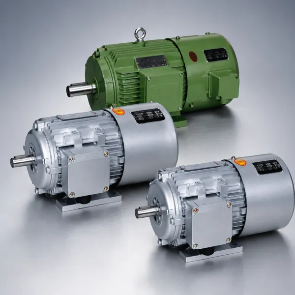
The Korea Ever-Power YVF2 series is the correct motor specification for all centrifugal pump VFD retrofit and new-build applications. It combines IC416 forced cooling for full torque at any speed, Class H VFD-duty winding insulation for long-term resistance to PWM voltage spikes, and PTC thermistor winding protection as standard. The YVF2 uses the same IEC 72-1 frame dimensions as the standard Y2 series, allowing it to replace an existing Y2 motor in a pump retrofit without modification to the pump baseplate, coupling, or piping. The full YVF2 range is available in the VFD inverter-duty motor product section.
| Power range | 0.75–200 kW |
| Poles (pump) | 2P (2,900 rpm) or 4P (1,450 rpm) |
| Cooling | IC416 forced blower |
| Insulation | Class H, VFD-duty formulation |
| Speed range | 0–120 Hz |
| PTC thermistors | Standard 3× in stator winding |
| Protection | IP54 standard |
| Frame compatibility | IEC 72-1 — same as Y2 series |
7. Pump VFD Applications
Building Services Chilled Water Pump
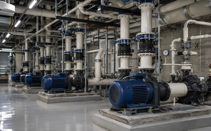
Primary and secondary chilled water pump sets in commercial building HVAC systems are the highest-impact application for VFD retrofit due to their size (7.5 to 90 kW), continuous operation (8,000 hours per year), and highly variable load profile (full load only during peak summer days). VFD retrofit with YVF2 motors on building services pumps regularly achieves 40 to 60 percent reduction in pump energy consumption, with payback periods below 12 months in most buildings with existing DOL or star-delta pump starters. |

Industrial Process Cooling Water
Process cooling water pumps supplying heat exchangers, reactors, and compressor cooling circuits in chemical and manufacturing plants operate at highly variable throughput as process loads change with production schedule and ambient temperature. YVF2 pump drives modulated by a cooling water return temperature or pressure differential signal maintain the minimum required cooling duty while reducing pump energy by 30 to 50% compared to fixed-speed operation with bypass valve control. |
Municipal water supply booster pumps and building pressure booster sets with VFD maintain constant outlet pressure across wide flow range variations. YVF2 2-pole (2,900 rpm) 3.0 to 30 kW covers most pressure booster applications.
Agricultural irrigation pump stations with variable irrigation demand and rising main systems benefit from VFD speed control to maintain constant discharge pressure as field valve positions change. YVF2 4-pole 11 to 90 kW for main irrigation pump drives.
Jockey pump for fire system pressure maintenance operates intermittently at very low flow to compensate for system leakage. VFD speed control eliminates on-off cycling, maintaining constant pressure with far fewer starts and eliminating pressure transients from repeated DOL starting.
Steam condensate return pumps in industrial boiler systems. Condensate return volume varies with steam demand. VFD speed control on the condensate pump eliminates overflow to drain and reduces pump wear from frequent on-off cycling against a condensate level float switch.


8. Frequently Asked Questions
Edited by Cxm