1. Why a Standard Motor Fails on VFD Supply
A variable frequency drive outputs a pulse-width modulated (PWM) voltage waveform rather than a pure sinusoidal supply. Although the fundamental frequency and average voltage can be accurately controlled to achieve variable speed, the rapid switching transitions in the PWM waveform create voltage spikes that can reach 2 to 3 times the supply voltage at the motor terminals when the cable length between drive and motor exceeds a few metres. These voltage spikes stress the winding insulation in ways that standard motor insulation systems were not designed to withstand.
PWM voltage spikes can reach 1,200 V or more at the motor terminals on a 380 V drive system. Standard motor winding insulation is tested to approximately 1,000 V and will degrade from repetitive exposure to these spikes. The failure typically begins at the first coil turn, which receives the full voltage spike before the wavefront is attenuated along the winding. Over weeks to months, partial discharge damages the turn-to-turn insulation, eventually causing a winding short circuit.
A standard IC411 (TEFC) motor relies on its shaft-mounted fan to circulate cooling air over the frame. At low speed under VFD control, the fan turns slowly and delivers far less cooling airflow. At 25 percent of rated speed (for example, 360 rpm on a 4-pole motor), the cooling fan delivers approximately 6 percent of rated airflow (proportional to speed). The motor winding losses remain high at full torque, but cooling capacity is almost absent — causing rapid overheating if the motor runs at full torque at low speed.
PWM switching creates common-mode voltages on the motor shaft relative to earth. When the shaft voltage exceeds the lubricant film dielectric breakdown voltage in the bearing, a discharge current flows through the bearing ball-to-race contact. Repeated discharges erode the bearing raceway surface, producing a characteristic frosted or fluted appearance. The bearing becomes progressively noisier and fails prematurely — typically in 6 to 18 months compared to 20,000+ hours on sinusoidal supply.
2. VFD Motor Design Features Explained
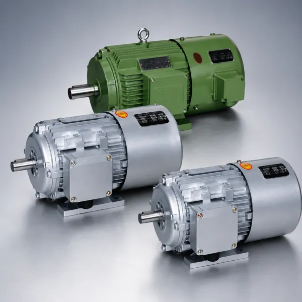
A VFD motor, such as Korea Ever-Power’s YVF2 series, incorporates specific engineering modifications to address each of the three failure mechanisms described above. These features make the motor suitable for continuous operation at any speed within the rated range without accelerated ageing.
VFD motors use Class H insulation (180°C rated) with corona-resistant enamelled wire for the stator winding. The corona-resistant (CR) wire has an additional coating that resists partial discharge at voltage levels above the insulation threshold. The slot liner material is upgraded from standard polyester to an aramid-based material with higher dielectric strength. The winding impregnation uses a VPI (vacuum pressure impregnation) resin system that eliminates voids in the coil insulation where partial discharge could initiate. Together, these measures raise the effective impulse voltage withstand of the winding from approximately 1,000 V (standard) to 1,350 V or higher, well above the peak VFD spike voltage on a 380 V system.
The IC416 cooling system replaces the shaft-mounted fan (IC411) with a separately powered external blower motor mounted on the non-drive end of the main motor. The blower runs at fixed speed continuously, independent of the main motor shaft speed, maintaining rated cooling airflow even when the main motor runs at near-zero speed. This allows the VFD motor to deliver full rated torque from 0 rpm to rated speed — the 10:1 constant torque speed range — without any thermal derating. Korea Ever-Power YVF2 series blower motors are rated 380 V 50 Hz three-phase, typically 50 to 250 W depending on the main motor frame size.
Korea Ever-Power YVF2 series motors include PTC (Positive Temperature Coefficient) thermistor sensors embedded in the stator winding at the hottest point of each phase. PTC thermistors have a sharp resistance increase at a defined trip temperature (typically 130°C or 150°C). The thermistors connect to a PTC relay module in the VFD control panel, which trips the drive if any winding reaches the set temperature. This provides direct winding temperature protection independent of the external thermal overload relay, which only monitors motor current and cannot directly detect winding overtemperature caused by cooling system failure or excessive ambient temperature.
To interrupt the bearing current discharge path, YVF2 series motors above 75 kW are fitted with an insulated bearing sleeve in the non-drive-end bearing housing. The sleeve provides electrical isolation between the bearing outer ring and the motor end shield, preventing common-mode shaft voltage from completing a circuit through the NDE bearing. The drive-end bearing remains uninsulated to provide the required earth reference. An earthing brush (shaft grounding brush) may also be specified for very long cable runs or sensitive drive configurations where NDE bearing insulation alone is insufficient.
3. Cooling at Variable Speed: IC411 vs IC416
| Property | IC411 (Standard TEFC) | IC416 (VFD Motor Blower) |
|---|---|---|
| Cooling airflow source | Shaft-mounted fan, speed proportional to motor shaft | Separate constant-speed blower motor, independent of main shaft |
| Cooling at 10% speed | ~0.1% of rated cooling capacity | 100% of rated cooling capacity |
| Constant torque speed range | Typically 50–100% of rated speed (2:1 or less) | 0–100% of rated speed (10:1 or greater) |
| Additional supply needed | None | 380 V three-phase for blower motor (50–250 W) |
| Noise level at low speed | Reduced (fan turns slowly) | Constant blower noise regardless of motor speed |
| Typical applications | Variable torque loads (fans, pumps) with speed range above 50% rated | Constant torque loads at wide speed range: extruders, conveyors, machine tools, hoists |
Note for centrifugal fan and pump drives: for variable torque loads where speed rarely drops below 50 percent of rated, a standard motor with IC411 cooling may be adequate for VFD use because the centrifugal load naturally reduces torque at reduced speed, keeping winding temperatures manageable even with reduced fan cooling. However, the winding insulation reinforcement is still required regardless of the load type to protect against PWM voltage spikes.
4. Bearing Current and How to Prevent It
Bearing current damage is one of the most insidious failure modes in VFD-driven motors because it produces no immediate symptoms. The motor runs normally, with normal current and temperature, but the bearings are being progressively damaged by microscopic electrical discharges. The first symptom is typically an audible roughness in bearing rotation, by which time raceway fluting (a regular pattern of circumferential grooves on the bearing inner or outer race) is already established and bearing replacement is necessary.
Ceramic coating on bearing outer ring or insulated bearing sleeve in end shield. Breaks the discharge circuit at the NDE bearing. Standard on YVF2 above 75 kW. Most cost-effective solution for motors above 75 kW.
Carbon or silver-loaded brush rides on motor shaft, providing a low-impedance path to earth for common-mode shaft voltage. Discharges shaft voltage to earth before it can build to bearing lubricant breakdown level. Effective on all motor sizes; requires periodic brush replacement.
LC filter installed between VFD output and motor cable limits the voltage rise rate of PWM pulses at the motor terminals. Reduces peak voltage spike amplitude and slows the voltage wavefront, reducing both insulation stress and common-mode current magnitude. Recommended for cable runs above 50 metres.
Toroidal inductor on the drive output cable attenuates the common-mode current that creates shaft voltage. Often used in combination with a shaft grounding brush or NDE insulated bearing for comprehensive bearing current protection on large motors with long cable runs.
5. VFD Energy Saving Calculations
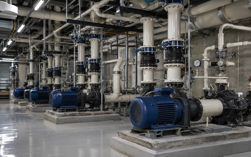
For centrifugal fan and pump loads, reducing motor speed with a VFD produces disproportionately large energy savings because power demand follows the cube law: power is proportional to the cube of speed. A 20 percent speed reduction yields a 49 percent power reduction.
This calculation assumes the system operates at 80% of maximum flow for most of the year. In practice, process flow demand varies, and the energy saving at partial flow is even greater than this example shows. VFD installation on centrifugal pump and fan applications typically achieves payback in 6 to 18 months at typical industrial electricity prices, making it one of the most financially attractive energy efficiency investments available to process plant operators.
6. Korea Ever-Power YVF2 Series VFD Motor
The YVF2 series is Korea Ever-Power’s inverter-duty motor range, designed for VFD variable speed applications across industrial drives. The full range is detailed in the VFD inverter-duty motor product section, covering 0.75 kW to 200 kW in IEC frame sizes 80M through 315M in 4-pole configuration, with 2-pole and 6-pole variants available on request.
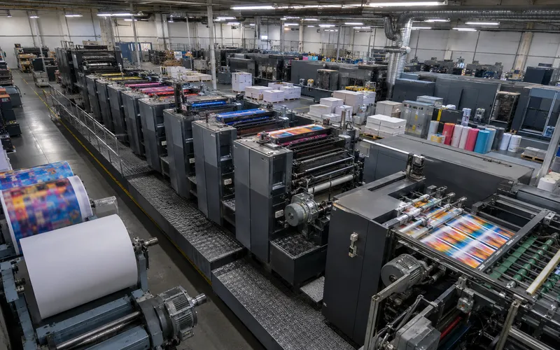
All YVF2 motors are built to IE3 efficiency (measured at 50 Hz sinusoidal supply per IEC 60034-30-1). The IC416 external blower enables full rated torque from 0 to 50 Hz (0 to 1,450 rpm for 4-pole) with no derating, and continued operation above 50 Hz up to 120 Hz (up to 3,500 rpm) with constant power characteristic above base speed. This wide operating range covers extruder drives, conveyor speed control, machine tool axis drives, and large fan and pump installations with long daily operating hours.
| Power range | 0.75 – 200 kW |
| Voltage | 380 V ± 5%, 50 Hz |
| Frequency range | 0 – 120 Hz |
| Cooling | IC416 external blower |
| Constant torque range | 10:1 (0 – 50 Hz) |
| Insulation | Class H, CR wire |
| Protection | IP54 (IP55 on request) |
| Thermistors | PTC, 3 per motor |
| NDE bearing (≥75 kW) | Insulated sleeve standard |
7. Frequently Asked Questions
Edited by Cxm