Korea Ever-Power · YVF2 Series · HVAC Drive Application Guide

Inverter-Duty Motor for HVAC Fan and Pump:
Why VFD Drives Need a Special Motor

A standard three-phase induction motor connected to a variable frequency drive (VFD) in an HVAC fan or pump application will typically fail within 2 to 5 years from winding insulation breakdown, bearing current damage, or overheating at low speed — none of which would occur if the motor were running on a fixed-frequency sinusoidal supply. Korea Ever-Power YVF2 inverter-duty motors are engineered to address all three failure modes, making them the correct and safe specification for all HVAC VFD applications above 0.75 kW.

IC416 Forced Cooling
Class H Insulation
Bearing Current Protection
Energy Saving P ∝ n³
0.75–200 kW

51%
Power saved at 80% fan speed
1–3 yr
Typical VFD payback period on HVAC fan
Class H
Insulation vs Class F in standard motors
IC416
Forced blower: full torque from 0 to 60 Hz
PTC
Thermistor winding protection standard

YVF2 inverter duty motor HVAC fan pump VFD speed control IC416 blower Korea Ever-Power

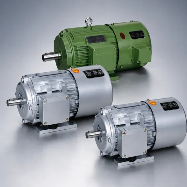
Korea Ever-Power YVF2 series inverter-duty motor — the independent blower on the non-drive end (visible at rear) provides IC416 forced ventilation that maintains full cooling airflow regardless of motor speed, eliminating the overheating risk that makes standard IC411 self-ventilated motors unsuitable for VFD operation at low speed in HVAC fan and pump drives.

1. Energy Saving: The Case for VFD on HVAC Fan and Pump Drives

HVAC fans and chilled water pumps in commercial and industrial buildings are typically designed to meet peak load conditions — the hottest day of the year or the maximum occupied building load. For 70 to 90 percent of operating hours, the actual demand is significantly below peak, yet a fixed-speed motor with a damper or valve runs at full power and wastes the excess capacity across a restriction. VFD speed control eliminates this waste by matching fan or pump speed to actual demand.

Worked Energy Saving Example — AHU Supply Fan
Without VFD (damper control):
Motor: 22 kW at full speed, 8,000 h/yr
Average load: 75% of peak
Annual consumption: 22 × 8,000 = 176,000 kWh
Annual cost at $0.13/kWh = $22,880
With VFD + YVF2 motor (speed control):
Average speed: 85% of full speed
Average power: 22 × (0.85)³ = 13.5 kW
Annual consumption: 13.5 × 8,000 = 108,000 kWh
Annual cost = $14,040 — saving $8,840/yr
Payback period: VFD system cost $4,500 ÷ $8,840/yr saving = 0.51 years (6 months)

This example illustrates why VFD speed control on HVAC fans and pumps typically has a payback period of 6 months to 2 years — making it one of the highest-return energy efficiency investments available in building services. The key is pairing the VFD with a YVF2 inverter-duty motor, not a standard Y2 motor, to ensure reliable long-term operation.

2. Why Standard Motors Fail on VFD Drives

A standard Y2 motor (IC411 self-ventilated, Class F insulation) connected directly to a VFD without motor-specific protection will experience three failure mechanisms that do not occur on sinusoidal fixed-frequency supply:

1. Insulation Breakdown from Voltage Spikes

VFD output is a pulse-width-modulated (PWM) waveform with switching voltage spikes of 1,000 to 1,600 V (depending on cable length and VFD switching frequency) that repeat at the carrier frequency of 2 to 16 kHz. Standard Class F winding insulation, designed for sinusoidal supply, degrades rapidly under repeated high-frequency voltage spikes. Partial discharge in the winding insulation progressively erodes the conductor insulation, causing turn-to-turn shorts within 2 to 4 years of VFD operation without adequate motor insulation specification.

2. Overheating at Low Speed

Standard IC411 motors use a shaft-mounted fan to cool the stator and winding — the cooling airflow is proportional to shaft speed. At 25 Hz (50% of rated speed), the cooling fan provides only approximately 25% of full-speed cooling airflow. However, at 25 Hz the motor still produces rated torque and therefore approximately 50% of rated power, which generates substantial heat that the fan cannot adequately dissipate. The winding temperature rises above the Class F limit, accelerating insulation ageing by 2x for every 10 K excess temperature (Montsinger Rule).

3. Bearing Current Damage

VFD PWM switching creates capacitive coupling between stator windings and the rotor shaft, inducing a common-mode voltage on the shaft. This shaft voltage discharges through the motor bearings (the lowest-resistance path to ground), causing high-frequency electrical discharge machining (EDM) of the bearing races and balls. Bearing current damage produces characteristic frosting and fluting patterns on the bearing race surface, which leads to increased vibration and bearing failure within 6 to 18 months on standard unprotected bearings running on high-carrier-frequency VFDs.

3. IC416 vs IC411: Cooling at Low Speed

IEC 60034-6 defines motor cooling circuit designations. IC411 is the standard self-ventilated cooling circuit — the motor cools itself through a shaft-mounted fan. IC416 is the forced-ventilated cooling circuit — a separate independently powered blower motor provides constant cooling airflow regardless of main motor speed.

Property IC411 (Standard Y2) IC416 (YVF2 Series)
Cooling fan drive Shaft-mounted (speed dependent) Independent blower motor (constant)
Cooling at 25 Hz (50% speed) ~25% of rated airflow 100% of rated airflow
Cooling at 5 Hz (10% speed) ~2% of rated airflow — critical 100% of rated airflow
Rated torque at low speed Derate below 30 Hz Full rated torque from 0 to rated frequency
Static holding torque (0 Hz) No cooling — not suitable Full cooling — static holding possible
VFD suitability Not recommended below 50 Hz continuous Designed for 0–120 Hz VFD operation

For HVAC fan drives that operate regularly below 40 Hz (80% of rated speed) — which is the normal operating range for most VFD-controlled AHU fans and cooling tower fans outside of peak load conditions — IC416 forced cooling is not optional. It is a fundamental requirement for safe and reliable long-term operation.

4. Class H Insulation for VFD Voltage Spikes

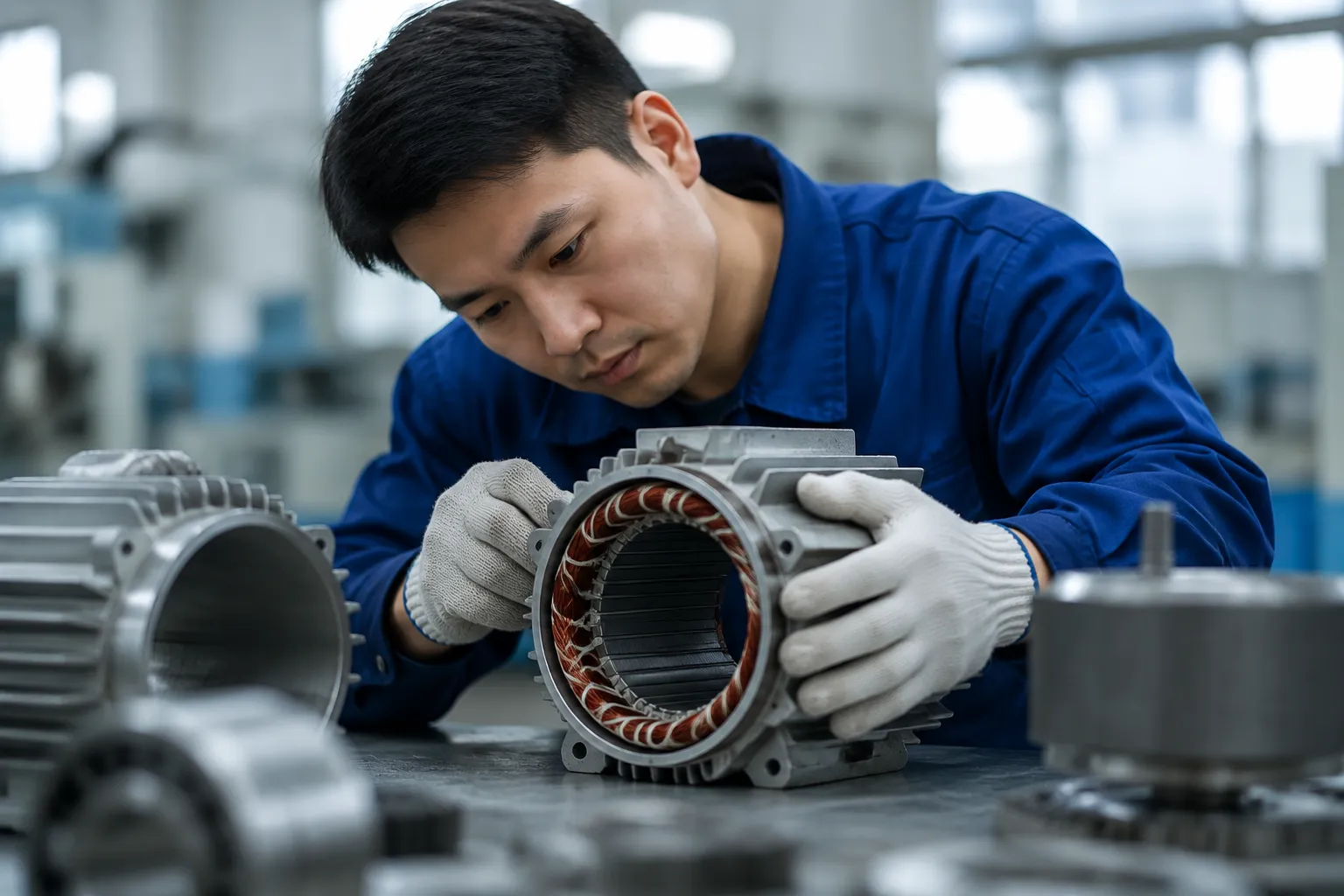
The YVF2 series uses Class H winding insulation (maximum continuous temperature 180°C) with a VFD-duty formulation that includes enhanced partial discharge resistance. Class H insulation in the YVF2 provides two layers of additional protection compared to the Class F insulation in a standard Y2 motor:

Higher voltage spike tolerance

VFD-duty Class H insulation in the YVF2 is formulated with a higher dielectric strength and a higher partial discharge inception voltage than standard Class F insulation. It is rated to withstand repetitive voltage spikes of up to 1,600 V peak (dV/dt up to 5,000 V/μs) without progressive insulation breakdown — matching the output characteristics of modern IGBT-based VFDs operating with cable runs up to approximately 50 m without additional output filtering.

Thermal reserve at operating temperature

Even with IC416 forced cooling, operating a motor at low speed with full torque generates more heat per unit of output power than at rated speed. The 25 K thermal reserve of Class H over Class F means the YVF2 winding runs at a lower fraction of its thermal limit under the same operating conditions, extending insulation life in accordance with the Montsinger Rule.

Insulation Comparison
Property Class F Class H
Max temp 155°C 180°C
Thermal reserve* 15 K 40 K
Relative life at 40°C ambient
VFD duty rating Standard VFD-duty
*Reserve above Class B rise (80 K) at 40°C ambient

5. Bearing Current Protection

The YVF2 series addresses VFD bearing current damage through a combination of bearing selection, insulation, and grounding design. The severity of bearing current depends on motor frame size, VFD carrier frequency, and cable length. Korea Ever-Power applies the following protection measures in the YVF2 series:

Insulated Non-Drive-End Bearing (Frame 180+)

For YVF2 motors in frames 180M and above, the non-drive-end (NDE) bearing is fitted in an insulated housing that breaks the shaft-to-bearing-to-frame current path. Bearing current is forced to find an alternative path to earth that does not include bearing surfaces, protecting the drive-end bearing from the bulk of the circulating current.

Shaft Grounding Ring (Optional)

A conductive microfibre shaft grounding ring provides a low-impedance path for common-mode shaft voltage to discharge to earth without passing through the bearing. Recommended for YVF2 motors above 11 kW on VFDs with carrier frequencies above 4 kHz, or for installations with long motor cables (above 30 m). Available as an option from Korea Ever-Power.

VFD-Side dV/dt Filter (Recommended for Long Cables)

A dV/dt output filter on the VFD reduces the rate of voltage rise of the PWM pulses, limiting peak overvoltage at the motor terminals. For motor-to-VFD cable runs above 50 m, a dV/dt filter reduces peak voltage at motor terminals to below the YVF2 insulation limit regardless of VFD switching frequency. Korea Ever-Power recommends VFD-side filters for HVAC fan installations with long cable routes from central VFD panels to remote AHUs.

6. YVF2 Specifications for HVAC Applications

The Korea Ever-Power YVF2 series is a purpose-designed inverter-duty motor for VFD applications in HVAC and industrial systems. The YVF2 is available in the VFD inverter-duty motor product section across the 0.75 to 200 kW power range in 2-pole and 4-pole configurations. The 4-pole (1,450 rpm) configuration is the standard for AHU fans, cooling tower fans, and chilled water pumps; the 2-pole (2,900 rpm) configuration is used for high-speed centrifugal fans and process pumps where the pump or fan is designed for 2,900 rpm operation.

YVF2 Key Specifications
Power range 0.75–200 kW
Cooling IC416 forced ventilation
Insulation Class H, VFD-duty
Speed range 0–120 Hz VFD supply
Protection IP54 standard
PTC thermistors Standard — connect to VFD PTC input
Voltage spike rating Up to 1,600 V peak
Poles 2P (2,900 rpm) / 4P (1,450 rpm)

7. HVAC Applications

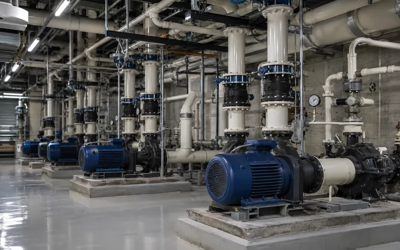
YVF2 VFD motor HVAC pump room chilled water pump variable speed energy saving

Chilled Water and Condenser Water Pumps

Primary and secondary chilled water pumps in central plant HVAC are the largest single energy consumer in most commercial buildings. YVF2 4-pole 7.5 to 75 kW paired with a building management system (BMS) controlled VFD delivers variable primary flow (VPF) control, reducing pump energy by 40 to 60 percent compared to constant volume systems. The VFD modulates pump speed to maintain differential pressure set point across the distribution system as zone valve positions change with load variation.

YVF2 VFD motor AHU fan air handling unit variable speed HVAC inverter duty

Air Handling Unit (AHU) Supply and Return Fans

Supply and return fans in large AHUs serving commercial offices, hospitals, data centres, and industrial facilities are the primary application for YVF2 motors in HVAC. Fan motors from 7.5 to 90 kW, VFD-controlled from a BMS or stand-alone HVAC controller to maintain supply air temperature and duct static pressure set points. Variable air volume (VAV) systems reduce fan speed as zone dampers close, saving fan energy proportionally to the cube of speed reduction.

Cooling Tower Fan

Induced-draft cooling tower fans use YVF2 4-pole 3.0 to 30 kW motors. VFD control modulates fan speed to maintain condenser water supply temperature, reducing fan energy by 50 to 70 percent compared to fixed-speed two-speed motors. Outdoor installation requires IP55; Class H insulation is important as the motor discharges warm humid air from the tower.

Boiler Feed Pump

Boiler feed pumps in industrial steam systems use YVF2 2-pole or 4-pole motors in 3.0 to 55 kW range. VFD control modulates feed flow to match steam demand, replacing the drum level control valve with direct speed control and saving 20 to 40 percent of pump energy in variable-demand steam systems.

Exhaust and Extract Fan

Kitchen exhaust, laboratory fume cupboard extract, and car park ventilation fans use YVF2 motors with CO or CO₂ demand-controlled VFD operation. Fan speed reduces to minimum during low-occupancy periods, saving 40 to 60 percent of fan energy in commercial building and public facility ventilation systems.

Compressor Inlet Guide Vane

Centrifugal chiller compressor capacity control using VFD-driven guide vane actuator motors or direct compressor VFD drive. YVF2 motors 0.75 to 7.5 kW for guide vane actuator duty. Full compressor VFD drive uses YVF2 at the rated compressor motor size, typically 30 to 200 kW for large chillers.

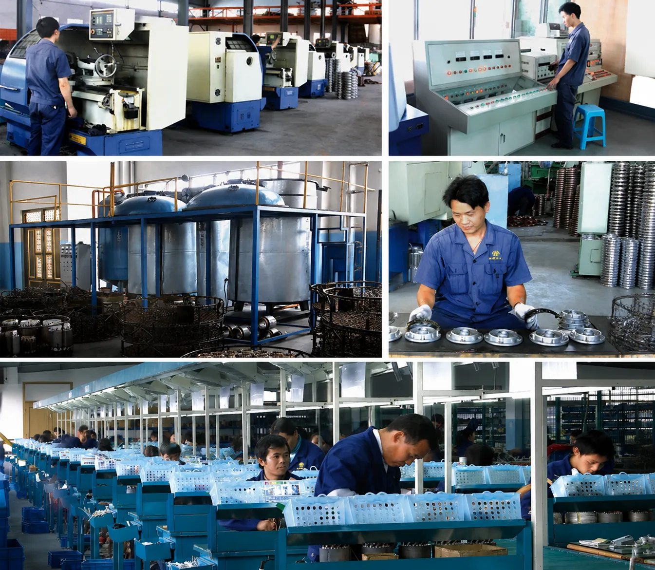
Korea Ever-Power YVF2 motor precision machining

Precision Machining

Korea Ever-Power VFD motor testing

VFD Performance Test

Korea Ever-Power CE IE3 certification

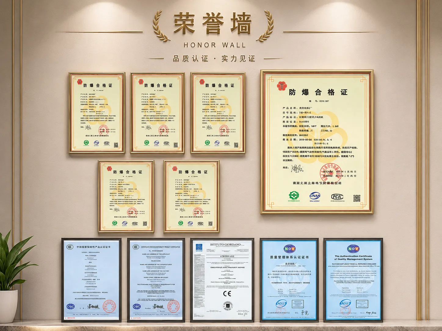
CE and ISO Certified

Korea Ever-Power global HVAC motor customers

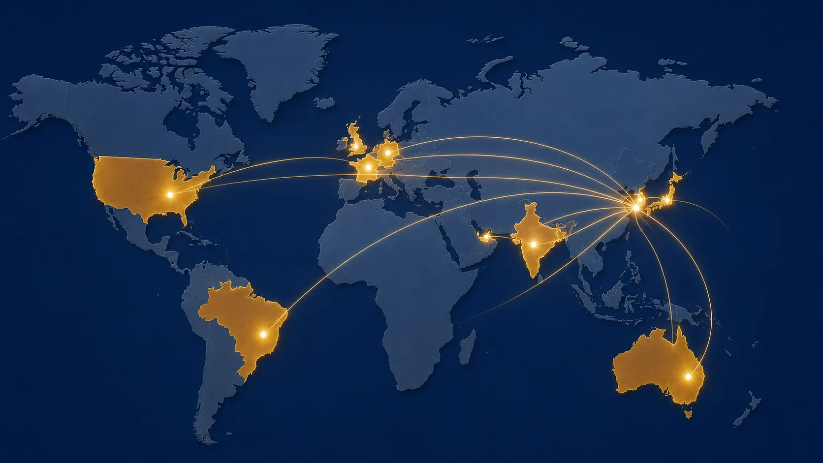
Global HVAC Customers

8. Frequently Asked Questions

Can I add a VFD to an existing standard Y2 motor on my AHU fan without changing the motor?

You can operate a standard Y2 motor on a VFD for short periods, but for continuous HVAC duty this approach has significant long-term risks. If the fan only operates between 40 and 50 Hz (80 to 100% of rated speed), the cooling reduction at low speed is modest and the standard insulation may not be seriously stressed, depending on cable length and VFD carrier frequency. However, any time the fan operates below 30 Hz for sustained periods — which is typical in variable air volume systems — the standard IC411 cooling becomes inadequate and the insulation is stressed by repeated PWM voltage spikes. For a reliable retrofit of an existing fan to VFD control, the preferred approach is to replace the Y2 motor with a YVF2 at the same frame size and power rating and connect the new motor to the VFD. The incremental cost of specifying a YVF2 over a Y2 is typically recovered within 6 to 12 months through extended motor service life alone.

Do PTC thermistors in the YVF2 motor connect directly to the VFD?

Yes — most modern VFDs include a PTC thermistor input circuit that monitors the motor winding temperature directly. The YVF2 is supplied with three PTC thermistors embedded in the stator winding (one per phase) connected to a terminal in the motor terminal box, separate from the main power terminals. Connect the PTC circuit to the VFD PTC input and configure the VFD to alarm and trip if the thermistor resistance exceeds the 3.3 kΩ trip threshold (which corresponds to a winding temperature approaching the Class H thermal limit). This provides a direct thermal protection that supplements the VFD electronic overload — the PTC protects against conditions that the electronic overload may not detect, such as blocked cooling air intake or sustained operation at low speed with high torque demand. Always enable the PTC protection — do not leave it disconnected.

What minimum speed can I run a YVF2 motor at for continuous HVAC fan duty?

The YVF2 with IC416 cooling can produce full rated torque at any speed from near-zero to 120 Hz, because the blower maintains full airflow independently of motor shaft speed. From a thermal perspective, there is no minimum speed limit for continuous operation. From a practical HVAC control perspective, centrifugal fans become inefficient below approximately 20 to 25 Hz (40 to 50% of rated speed) because the fan operates far from its design point — the flow drops approximately to the cube root of the power, but the system resistance may cause the fan to stall at very low speeds. Most HVAC VFD control systems set a minimum frequency of 20 to 25 Hz for centrifugal fan applications, which corresponds to 40 to 50% of rated speed, to maintain stable fan operation and adequate ventilation rates above the minimum air change requirement for the served space.


Korea Ever-Power · YVF2 Series · HVAC VFD Motor

Specifying a VFD Motor for Your HVAC Fan or Pump?

Korea Ever-Power YVF2 series: IC416 blower, Class H VFD-duty insulation, PTC thermistors, 0.75–200 kW, 2-pole and 4-pole. The correct motor for every HVAC VFD application.

View YVF2 Motor Range

Edited by Cxm