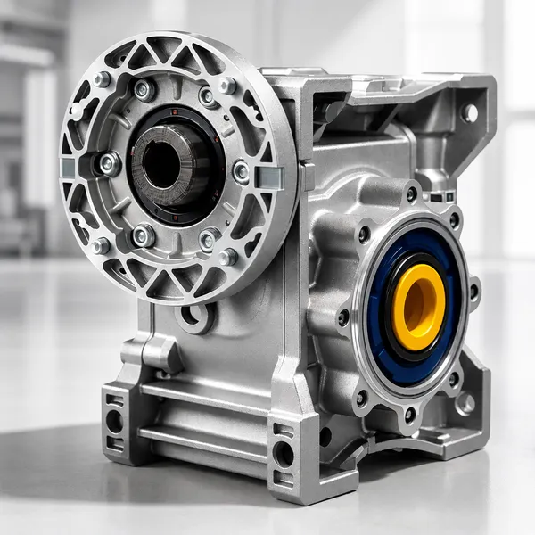
1. How a Worm Gear Reducer Works
A worm gear reducer consists of two main components: the worm (a helical screw shaft made from hardened alloy steel) and the worm wheel (a toothed wheel made from centrifugally cast bronze or ductile iron, mounted on the output shaft at 90 degrees to the worm shaft). The worm is directly connected to or integral with the input shaft driven by the motor. As the worm rotates, its helical threads engage with the teeth of the worm wheel, converting the high-speed rotary motion of the motor input into slow rotary motion of the output shaft at a right angle.
The gear ratio of a worm gear reducer is determined by the number of starts on the worm and the number of teeth on the worm wheel. For a single-start worm meshing with a 60-tooth worm wheel, the gear ratio is 60:1 — the output shaft completes one revolution for every 60 revolutions of the input shaft. Standard single-stage ratios in the Korea Ever-Power RV/NMRV series range from 5:1 to 100:1, covering output speeds from 29 rpm (100:1 at 2,900 rpm motor input) down to 290 rpm (5:1 at 1,450 rpm 4-pole motor input).
20CrMnTi alloy steel, case-hardened to HRC 56–62, ground to Ra 0.4 μm finish. The hardened and ground worm shaft surface provides the wear resistance needed to maintain the precise tooth profile that determines backlash and efficiency over the service life of the reducer.
Centrifugally cast phosphor bronze (CuSn12) or ductile iron (for larger sizes). Bronze provides the conformability needed to develop a full contact pattern against the hardened steel worm under load, and the sacrificial wear behaviour that protects the harder worm from surface damage under misalignment or shock loading.
2. Self-Locking: When and Why It Applies
Self-locking is the property by which a worm gear reducer cannot be back-driven — that is, torque applied to the output shaft cannot rotate the worm shaft. This occurs when the worm lead angle is less than the friction angle between the worm and worm wheel materials. For a single-thread worm at typical steel-on-bronze friction coefficients, self-locking occurs at gear ratios above approximately 20:1 to 30:1, depending on the specific worm geometry and lubricant viscosity.
Inclined conveyors: when the motor stops, the load on the inclined belt cannot roll back because the worm gear reducer holds the output shaft stationary under gravity loading. Lifting tables and vertical positioning stages: the platform remains at its set height when the motor is de-energised without a separate brake. Valve actuators: the valve remains at its set position without continuous power to an electromagnetic holding device. In all these applications, the self-locking worm gear reducer provides a passive, failsafe holding function at no additional cost or complexity.
Self-locking is not a certified safety mechanism and should never be relied upon for life-safety holding applications (man-riding hoists, safety gates, suspended loads over people). The self-locking property can be lost if lubricant viscosity drops under elevated temperature, if vibration is present in the system, or if the worm gear ratio is near the borderline (25:1 to 35:1 range). For safety-critical holding, a brake motor (Korea Ever-Power Y2EJ series) or a separate certified safety brake is required in addition to or instead of relying on worm gear self-locking.
Self-locking reference: NMRV and RV series worm gear reducers at ratios of 40:1 and above are reliably self-locking under normal operating conditions with standard gear oil viscosity. Ratios of 20:1 to 30:1 may or may not be self-locking depending on worm lead angle and operating temperature. Ratios below 15:1 are generally not self-locking.
3. RV and NMRV Series Overview
The Korea Ever-Power RV and NMRV series are aluminium alloy worm gear reducers that accept a three-phase induction motor directly on the IEC B5 flange input. The “NMR” prefix denotes the refined aluminium alloy housing (compared to the original cast iron RV design); the “V” suffix indicates the integral IEC motor flange. The housing numbers (025, 030, 040, 050, 063, 075, 090, 110, 130, 150) correspond to the centre distance between the worm shaft and worm wheel shaft axes in millimetres.
Korea Ever-Power NMRV units are available with hollow-shaft output (for direct shaft mounting without a separate coupling), solid output shaft in one or both directions, and a torque arm accessory for reaction force take-out. The full gearbox range with specifications is available in the worm gear reducer product section.
| Size | Max Input (kW) | Max Output Torque |
|---|---|---|
| NMRV 025 | 0.06 | 4 N·m |
| NMRV 030 | 0.09 | 8 N·m |
| NMRV 040 | 0.18 | 25 N·m |
| NMRV 050 | 0.55 | 70 N·m |
| NMRV 063 | 1.1 | 130 N·m |
| NMRV 075 | 2.2 | 240 N·m |
| NMRV 090 | 4.0 | 400 N·m |
| NMRV 110 | 7.5 | 700 N·m |
| NMRV 130 | 11 | 1,100 N·m |
| NMRV 150 | 22 | 2,000 N·m |
4. Gear Ratio, Output Torque and Efficiency
The output torque of a worm gear reducer is the motor shaft torque multiplied by the gear ratio and the gearbox efficiency, minus any mechanical losses. For a 4-pole motor at 1,450 rpm producing 4.0 kW (rated torque 26.4 N·m), connected to an NMRV 090 with a 40:1 ratio and 68 percent efficiency: output torque = 26.4 × 40 × 0.68 = 717 N·m at 36 rpm output. This is why even a modest 4 kW motor with a worm gear reducer can drive a heavily loaded slow conveyor or a large agitator — the torque multiplication at the gearbox output more than compensates for the efficiency loss at high ratios.
| Ratio | Output Speed (4P, 1450 rpm) | Typical Efficiency | Self-Locking? | Typical Use |
|---|---|---|---|---|
| 5:1 | 290 rpm | 88–92% | No | High-speed conveyors, fans, light agitators |
| 10:1 | 145 rpm | 82–87% | No | Medium-speed conveyors, packaging drives |
| 20:1 | 72 rpm | 75–82% | Borderline | Slow conveyors, agitators, winding machines |
| 40:1 | 36 rpm | 65–75% | Yes | Inclined conveyors, lifting tables, valve drives |
| 60:1 | 24 rpm | 55–65% | Yes | Slow dosing, stirrers, barrier gate drives |
| 100:1 | 14.5 rpm | 40–55% | Yes | Very slow drives: solar trackers, pot stirrers, precision positioners |
Efficiency note: worm gear efficiency decreases significantly at high ratios due to the sliding contact between worm and worm wheel. At 100:1 ratio, 45 to 60 percent of the input power is converted to heat in the gearbox. For continuous duty applications at high ratios (above 60:1), verify the gearbox thermal rating is not exceeded — the gearbox may need to be sized one step larger than the required torque to stay within the thermal limit at the operating cycle.
5. Thermal Rating and Duty Cycle
Because worm gear reducers generate significant heat through friction losses (especially at ratios above 30:1), the gearbox housing temperature during continuous operation is an important design constraint. Korea Ever-Power NMRV series reducers are thermal-rated for a maximum housing temperature of 80°C at 40°C ambient in S1 continuous duty at the rated input power. At high ratios and high input powers, the thermal rating may be the limiting factor rather than the mechanical torque rating.
The thermal power rating (P-th) of each NMRV size and ratio is published in the Korea Ever-Power gearbox data sheet. P-th is the maximum continuous input power that keeps the housing below 80°C in a 40°C ambient environment with the standard natural convection aluminium housing and no added cooling. At 50°C ambient, derate by 10 to 15 percent. At 60°C ambient, derate by 20 to 25 percent or add a cooling fan kit to the gearbox.
For intermittent duty applications (conveyor not running continuously; packaging machine with frequent starts and stops), the thermal rating can be increased above the S1 continuous rating. The Korea Ever-Power NMRV data sheet provides a duty factor correction table that allows the thermal input power rating to be increased by 15 to 40 percent for intermittent duty cycles with adequate rest periods for cooling between running periods.
6. Gearmotor Combinations: NMRV Plus Three-Phase Motor
Korea Ever-Power supplies the NMRV worm gear reducer matched and assembled with a Y2 series three-phase induction motor as a complete gearmotor unit. The motor’s IEC B5 flange connects directly to the NMRV input flange — no coupling, no adapter plate, and no separate alignment procedure. The combined unit is delivered as a single bolt-down component ready for installation. These gearmotor assemblies are detailed in the gearmotor combination product section.
For applications requiring higher output torque than a single NMRV unit can provide, Korea Ever-Power supplies double-stage worm gearmotor units — two NMRV reducers in series, providing gear ratios from 100:1 to 7,500:1. At 7,500:1 ratio, a 4-pole motor at 1,450 rpm produces an output speed of approximately 0.19 rpm (one revolution every 5 minutes) — suitable for very slow drives such as solar trackers and tide-control gates.
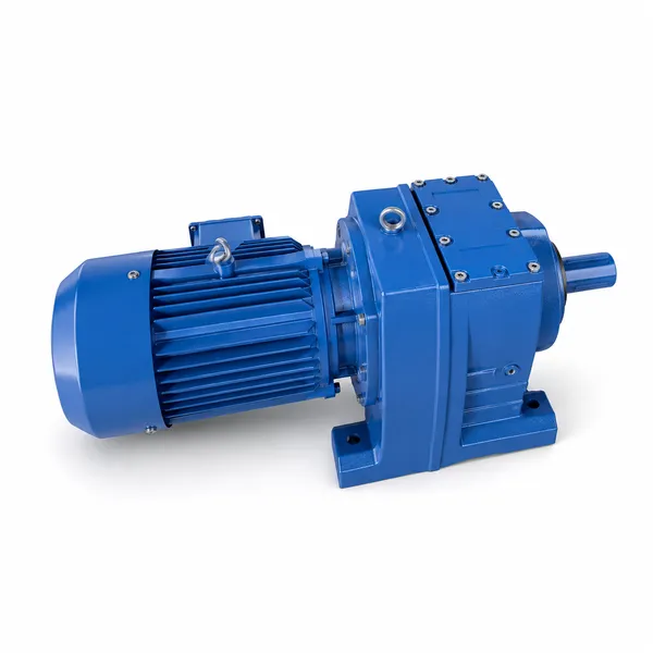
7. Application Areas
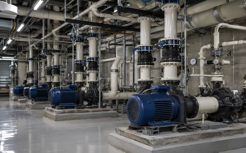
Pumps, Fans and HVAC
Cooling tower fan drives, circulation pump drives, and ventilation fan drives for HVAC systems use NMRV 050 to NMRV 090 worm gear reducers at 10:1 to 30:1 ratios. The compact right-angle output allows the motor to be positioned alongside rather than in-line with the driven shaft, reducing the length of the drive train and simplifying maintenance access. For centrifugal pump drives where VFD speed control is used, the NMRV gearbox provides the fixed ratio step-down while the VFD trims the speed over the operating range. |
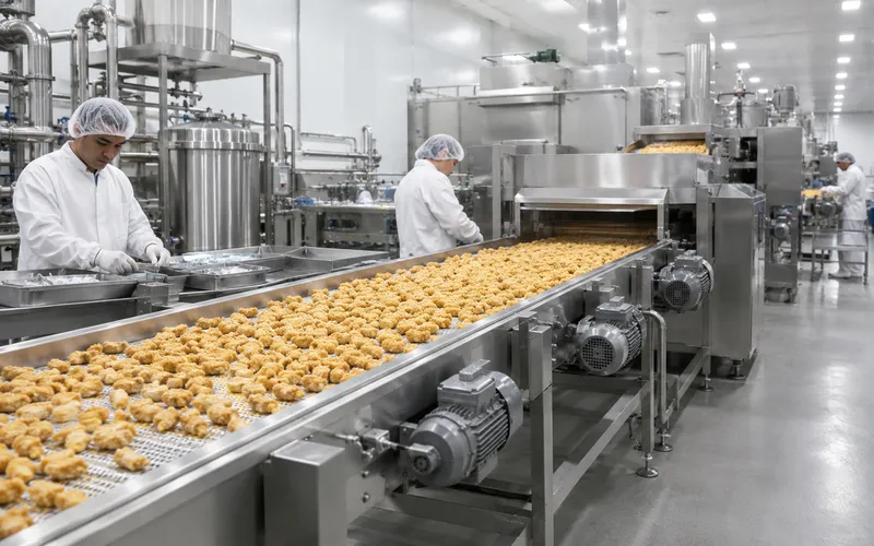
Food Processing and Packaging
Conveyor drives, mixer drives, filling machine drives, and labelling machine drives in food processing and packaging facilities use NMRV gearmotor units at ratios of 20:1 to 60:1. The self-locking property at 40:1 and above prevents conveyor runback on inclined lines when the motor stops. For food hygienic areas, the NMRV aluminium housing with IP65 protection and food-grade synthetic gear oil (H1 NSF listed) provides the washdown resistance required without the premium cost of a full stainless steel gearbox. |
Roller conveyor drives, pallet conveyor drives, and accumulation conveyor drives. NMRV 063 to NMRV 090 at 20:1 to 40:1 is the standard gearmotor specification for roller conveyor drives at 10 to 60 m/min belt speed.
Mixing vessel agitators, reactor stirrer drives, and dosing pump drives. High-ratio NMRV at 40:1 to 100:1 with explosion-proof motor option for Zone 2 areas where the YB2 explosion-proof motor is paired with an NMRV gearbox.
Feed auger drives, manure spreader drives, and grain handling auger drives use NMRV 075 to NMRV 110 at 20:1 to 60:1 for the compact torque density and self-cleaning worm tooth geometry that handles abrasive or fibrous material ingress better than helical gears.
Theatre fly loft drives, curtain track drives, and architectural shading system drives use NMRV gearmotors at 40:1 to 100:1. The self-locking property provides passive load holding at any position without a separate brake, critical for overhead loads above occupied areas.
8. Frequently Asked Questions
Edited by Cxm