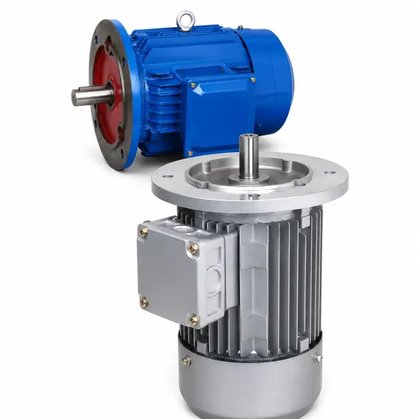
2. Κύρια εξαρτήματα και οι λειτουργίες τους
3. Τύποι κλουβιού σκίουρου έναντι τύπων ρότορα τραύματος
4. Επεξήγηση βασικών ηλεκτρικών προδιαγραφών
5. Κατηγορίες Απόδοσης: IE1, IE2, IE3, IE4
6. Βαθμολογίες IP και Κλάσης Μόνωσης
7. Τυπικές εφαρμογές ανά κλάδο
8. Συχνές ερωτήσεις
1. Πώς λειτουργεί ένας τριφασικός επαγωγικός κινητήρας
Ένας τριφασικός επαγωγικός κινητήρας λειτουργεί με βάση μια αρχή που ανακάλυψε ο Νίκολα Τέσλα το 1887: όταν τρεις ημιτονοειδείς τάσεις AC με απόσταση 120 μοιρών εφαρμόζονται σε τρία σετ περιελίξεων στάτορα διατεταγμένων γύρω από ένα κυλινδρικό πλαίσιο, δημιουργούν ένα περιστρεφόμενο μαγνητικό πεδίο στο εσωτερικό του κινητήρα. Αυτό το περιστρεφόμενο πεδίο περιστρέφεται με σύγχρονη ταχύτητα, η οποία ισούται με 60 φορές τη συχνότητα τροφοδοσίας διαιρούμενη με τον αριθμό των ζευγών πόλων (για παράδειγμα, στα 50 Hz με 2 πόλους: 3.000 σ.α.λ. με 4 πόλους: 1.500 σ.α.λ.).
Το περιστρεφόμενο μαγνητικό πεδίο διαπερνά τους αγωγούς του ρότορα. Επειδή οι αγωγοί του ρότορα είναι κλειστά κυκλώματα (βραχυκυκλωμένες ράβδοι σε σχεδιασμό κλωβού σκίουρου), η μεταβαλλόμενη μαγνητική ροή προκαλεί τάση σε αυτούς σύμφωνα με τον νόμο της ηλεκτρομαγνητικής επαγωγής του Faraday. Αυτή η επαγόμενη τάση οδηγεί ρεύματα μέσω των ράβδων του ρότορα. Αυτά τα ρεύματα του ρότορα αλληλεπιδρούν με το περιστρεφόμενο μαγνητικό πεδίο για να παράγουν μια δύναμη στους αγωγούς του ρότορα και ο ρότορας αρχίζει να περιστρέφεται προς την κατεύθυνση του πεδίου — αλλά πάντα ελαφρώς πιο αργά από την σύγχρονη ταχύτητα.
Αυτή η διαφορά ταχύτητας μεταξύ του σύγχρονου πεδίου και της πραγματικής ταχύτητας του ρότορα ονομάζεται ολίσθημαΗ ολίσθηση είναι απαραίτητη: εάν ο ρότορας λειτουργούσε με ακριβώς σύγχρονη ταχύτητα, δεν θα υπήρχε σχετική κίνηση μεταξύ των αγωγών πεδίου και ρότορα, ούτε επαγόμενη τάση, ούτε ρεύμα ρότορα και ούτε ροπή στρέψης. Σε πλήρες φορτίο, οι τυπικές τιμές ολίσθησης κυμαίνονται από 1 έως 5 τοις εκατό για τους βιομηχανικούς τριφασικούς επαγωγικούς κινητήρες τύπου squirrel-cage.
Η ομορφιά αυτού του σχεδιασμού έγκειται στο ότι δεν υπάρχει ηλεκτρική σύνδεση μεταξύ της τροφοδοσίας του στάτη και του ρότορα. Η ενέργεια μεταφέρεται εξ ολοκλήρου μέσω μαγνητικής επαγωγής διαμέσου ενός διακένου αέρα 0,2 έως 0,5 mm. Αυτό εξαλείφει τις ψήκτρες, τους δακτυλίους ολίσθησης και τους συλλέκτες, καθιστώντας τον τριφασικό επαγωγικό κινητήρα με σκίουρο-κλουβί την απλούστερη και πιο αξιόπιστη περιστρεφόμενη μηχανή σε βιομηχανική χρήση.
2. Κύρια εξαρτήματα και οι λειτουργίες τους
Κάθε τριφασικός επαγωγικός κινητήρας μοιράζεται την ίδια βασική αρχιτεκτονική ανεξάρτητα από την ονομαστική ισχύ ή τον κατασκευαστή. Η κατανόηση της λειτουργίας κάθε εξαρτήματος βοηθά στην επιλογή, την εγκατάσταση, την αντιμετώπιση προβλημάτων και τον προγραμματισμό συντήρησης του κινητήρα.
Το σταθερό εξωτερικό συγκρότημα. Αποτελείται από έναν πυρήνα από πυριτιούχο χάλυβα τοποθετημένο στο πλαίσιο του κινητήρα, με τρία σετ χάλκινων περιελίξεων που εισάγονται σε εγκοπές γύρω από την εσωτερική περιφέρεια. Η τριφασική τροφοδοσία συνδέεται με αυτά τα περιελίξεις, δημιουργώντας το περιστρεφόμενο μαγνητικό πεδίο. Οι στρώσεις στάτη μειώνουν τις απώλειες από δινορεύματα. Οι λεπτότερες στρώσεις σημαίνουν χαμηλότερες απώλειες σιδήρου και υψηλότερη απόδοση.
Το περιστρεφόμενο εσωτερικό συγκρότημα. Σε έναν κινητήρα με σκίουρο-κλωβό, ο πυρήνας του ρότορα είναι επίσης κατασκευασμένος από ελασματοποιημένο πυριτιούχο χάλυβα, με ράβδους αλουμινίου ή χαλκού χυτευμένες ή εισαγόμενες στις εγκοπές του ρότορα. Οι ράβδοι βραχυκυκλώνονται και στα δύο άκρα με αγώγιμους δακτυλίους στα άκρα, σχηματίζοντας ένα σχήμα κλωβού. Ο άξονας του ρότορα μεταδίδει μηχανική ροπή στο κινούμενο φορτίο. Δεν απαιτείται εξωτερική ηλεκτρική σύνδεση με τον ρότορα.
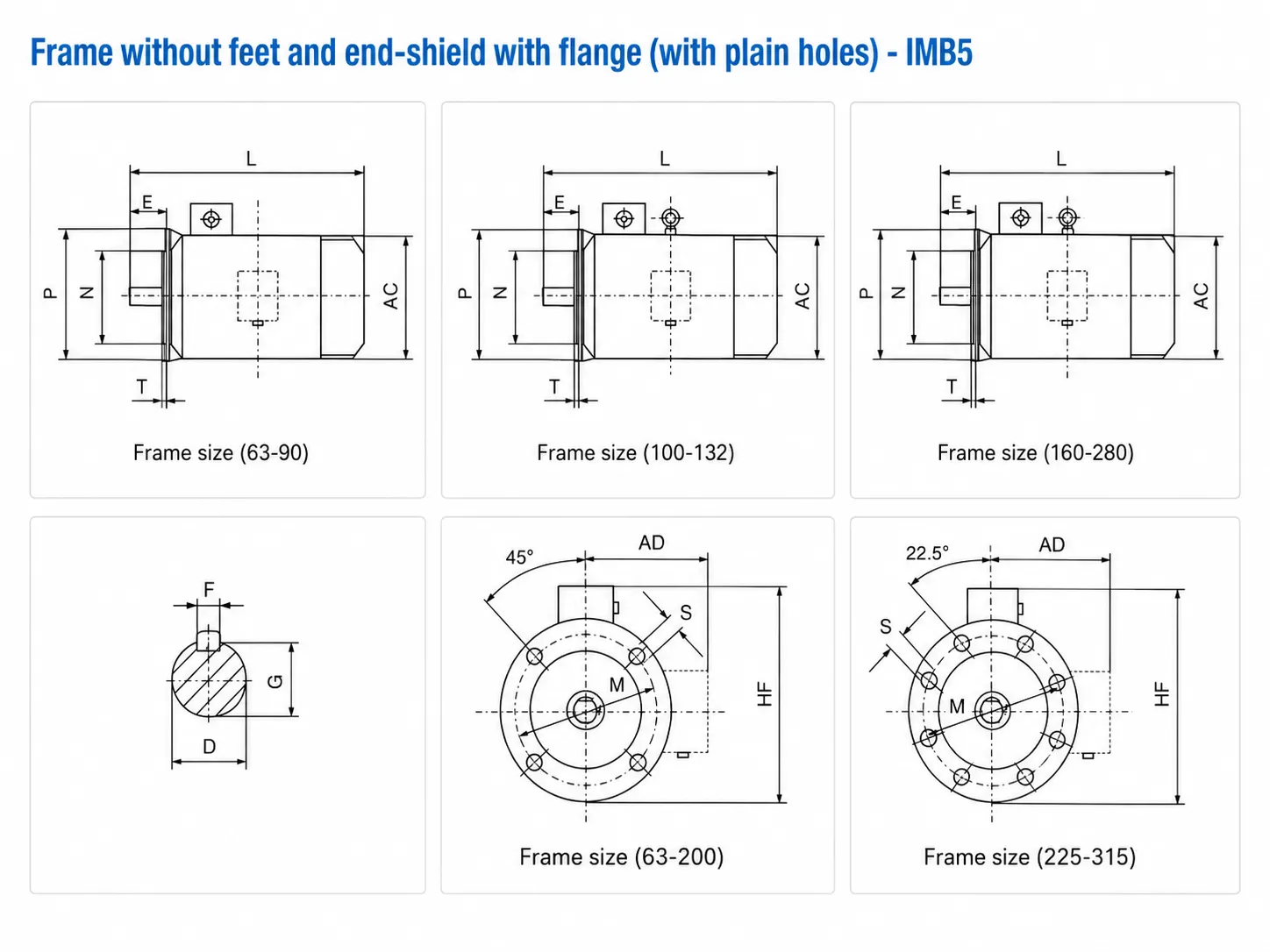
Το πλαίσιο από χυτοσίδηρο ή αλουμίνιο στεγάζει τον στάτορα και παρέχει δομική στήριξη, απαγωγή θερμότητας μέσω εξωτερικών πτερυγίων ψύξης και προστασία για τις εσωτερικές περιελίξεις. Οι ακραίες ασπίδες (τερματικές πλάκες) κλείνουν κάθε άκρο του πλαισίου και φέρουν τα ρουλεμάν που στηρίζουν τον άξονα του ρότορα. Οι διαστάσεις του πλαισίου ακολουθούν τα πρότυπα IEC 72-1, έτσι ώστε οι κινητήρες από διαφορετικούς κατασκευαστές να είναι μηχανικά εναλλάξιμοι στην ίδια ονομασία πλαισίου.
Τα ρουλεμάν υποστηρίζουν τον άξονα του ρότορα και διατηρούν το ακριβές διάκενο αέρα μεταξύ του ρότορα και του στάτορα. Τα ρουλεμάν βαθιάς αυλάκωσης είναι στάνταρ για πλαίσια έως 250 mm. Τα μεγαλύτερα πλαίσια χρησιμοποιούν έναν συνδυασμό ρουλεμάν κυλίνδρων στο άκρο κίνησης (για τη διαχείριση ακτινικού φορτίου από ιμάντα ή αλυσίδα κίνησης) και ρουλεμάν στο άκρο εκτός κίνησης. Η διάρκεια ζωής των ρουλεμάν είναι συνήθως 20.000 έως 30.000 ώρες λειτουργίας σε ονομαστικό φορτίο και κανονική θερμοκρασία περιβάλλοντος.
Ένας πλαστικός ή μεταλλικός ανεμιστήρας είναι τοποθετημένος στο μη κινητήριο άκρο του άξονα, μέσα σε ένα κάλυμμα ανεμιστήρα με ανοίγματα εισόδου και εξόδου αέρα. Καθώς ο κινητήρας λειτουργεί, ο ανεμιστήρας τραβάει αέρα ψύξης πάνω από τα εξωτερικά πτερύγια του πλαισίου, απομακρύνοντας τη θερμότητα που παράγεται από τις απώλειες χαλκού στην περιέλιξη και τις απώλειες σιδήρου στον πυρήνα. Αυτή η διάταξη IC411 (εντελώς κλειστού ανεμιστήρα που ψύχεται) είναι το παγκόσμιο πρότυπο για βιομηχανικούς τριφασικούς επαγωγικούς κινητήρες.
Ένα χυτό κουτί πάνω ή δίπλα στο πλαίσιο του κινητήρα που περιέχει την πλακέτα ακροδεκτών για τη σύνδεση των καλωδίων τροφοδοσίας. Οι τυπικοί τριφασικοί επαγωγικοί κινητήρες έχουν έξι ακροδέκτες (U1, V1, W1, U2, V2, W2) που επιτρέπουν σύνδεση αστέρα ή τριγώνου. Η θέση του κουτιού ακροδεκτών μπορεί συνήθως να περιστραφεί σε τέσσερις θέσεις (πάνω, αριστερά, δεξιά, απέναντι από το άκρο του κινητήρα) για να ταιριάζει στην κατεύθυνση εισόδου του καλωδίου. Η ονομαστική τιμή IP του κουτιού ακροδεκτών αντιστοιχεί ή υπερβαίνει την ονομαστική τιμή πλαισίου.
3. Τύποι κλουβιού σκίουρου έναντι τύπων ρότορα τραύματος
Οι τριφασικοί κινητήρες διατίθενται σε δύο διαμορφώσεις ρότορα. Η επιλογή μεταξύ τους εξαρτάται από τις απαιτήσεις εκκίνησης, τις ανάγκες ελέγχου ταχύτητας και τα χαρακτηριστικά φορτίου.
| Ιδιοκτησία | Ρότορας με κλουβί σκίουρου | Ρότορας τραύματος (δακτύλιος ολίσθησης) |
|---|---|---|
| Κατασκευή ρότορα | Ράβδοι αλουμινίου ή χαλκού, βραχυκυκλωμένοι δακτύλιοι άκρων | Τριφασικά περιελιγμένα πηνία, συνδεδεμένα μέσω δακτυλίων ολίσθησης σε εξωτερική αντίσταση |
| Ρεύμα εκκίνησης | Υψηλή (5–8 × ονομαστικό ρεύμα στην εκκίνηση DOL) | Μειωμένη (εξωτερικά όρια αντίστασης εισροή) |
| Ροπή εκκίνησης | Καλή (1,8–3,0 × ονομαστική ροπή) | Άριστη (έως 2,5–3,5 × ονομαστική ροπή με πλήρη εξωτερική αντίσταση) |
| Έλεγχος ταχύτητας | Απαιτείται VFD για μεταβλητή ταχύτητα | Περιορισμένο εύρος στροφών μέσω εξωτερικής αντίστασης ρότορα (αναποτελεσματικό) |
| Συντήρηση | Ελάχιστο (μόνο ρουλεμάν) | Κανονικά (βούρτσες, δακτύλιοι ολίσθησης, εξωτερικές τράπεζες αντίστασης) |
| Κόστος | Χαμηλότερος | Υψηλότερη (κινητήρα + εξωτερικός εξοπλισμός αντίστασης) |
| Τυπικές εφαρμογές | Αντλίες, ανεμιστήρες, συμπιεστές, μεταφορικοί ιμάντες — η συντριπτική πλειοψηφία των βιομηχανικών συστημάτων κίνησης | Μεγάλοι γερανοί, ανυψωτικά μηχανήματα, μύλοι άλεσης υψηλής αδράνειας (παλαιές εφαρμογές) |
Σημείωση του κλάδου: Οι κινητήρες με περιελιγμένο ρότορα έχουν σε μεγάλο βαθμό αντικατασταθεί από κινητήρες με σκίουρο-κλωβό σε συνδυασμό με μετατροπείς συχνότητας (VFD) στις σύγχρονες εγκαταστάσεις. Οι VFD παρέχουν ακριβέστερο έλεγχο ταχύτητας, καλύτερη ενεργειακή απόδοση και χαμηλότερη συντήρηση από τους εκκινητές αντίστασης με περιελιγμένο ρότορα. Οι νέες εγκαταστάσεις τύπων περιελιγμένου ρότορα είναι σπάνιες εκτός από τις παλαιές περιπτώσεις αντικατάστασης.

4. Επεξήγηση βασικών ηλεκτρικών προδιαγραφών
Κάθε πινακίδα τύπου κινητήρα φέρει ένα σύνολο ονομαστικών τιμών που καθορίζουν το κανονικό σημείο λειτουργίας του κινητήρα. Αυτά τα στοιχεία αποτελούν τη βάση για την επιλογή του κινητήρα, τις ρυθμίσεις του ρελέ προστασίας, το μέγεθος του καλωδίου και τους υπολογισμούς του κόστους ενέργειας. Ο πλήρης οδηγός για την ανάγνωση αυτών των τιμών βρίσκεται στο τμήμα προϊόντος τριφασικού κινητήρα.
Η ισχύς εξόδου του άξονα σε πλήρες φορτίο. Αυτή είναι η ισχύς που παρέχει ο κινητήρας στον κινούμενο εξοπλισμό, όχι η ηλεκτρική ισχύς που καταναλώνεται από την παροχή. Ηλεκτρική ισχύς εισόδου = ισχύς άξονα διαιρούμενη με την απόδοση. Ένας κινητήρας 15 kW με απόδοση 92% καταναλώνει 16,3 kW από την παροχή σε πλήρες φορτίο.
Η τάση τροφοδοσίας στην οποία έχει σχεδιαστεί να λειτουργεί ο κινητήρας. Το παγκόσμιο πρότυπο τάσης τροφοδοσίας είναι 380 V (περιοχές IEC) ή 460 V (Βόρεια Αμερική). Οι κινητήρες διπλής τάσης (π.χ. 220V/380V) μπορούν να συνδεθούν σε δέλτα για 220 V ή σε αστέρα για 380 V. Η λειτουργία πάνω ή κάτω από την ονομαστική τάση κατά περισσότερο από 5 τοις εκατό προκαλεί υπερθέρμανση και μείωση της ροπής.
Το ρεύμα γραμμής που λαμβάνεται από την τροφοδοσία σε ονομαστική τάση και πλήρες φορτίο. Χρησιμοποιήστε αυτήν την τιμή για να διαστασιολογήσετε τα καλώδια τροφοδοσίας, τις ασφάλειες και τα ρελέ προστασίας κινητήρα. Το ρεύμα εκκίνησης (Ist) είναι συνήθως 5 έως 8 φορές το ονομαστικό ρεύμα για έναν κινητήρα με σκίουρο-κλωβό σε άμεση εκκίνηση, και διαρκεί 1 έως 10 δευτερόλεπτα μέχρι ο κινητήρας να φτάσει σε ταχύτητα λειτουργίας.
Η ταχύτητα περιστροφής του άξονα σε πλήρες φορτίο, η οποία είναι ελαφρώς χαμηλότερη από την σύγχρονη ταχύτητα λόγω ολίσθησης. Στα 50 Hz, οι τυπικές ονομαστικές ταχύτητες είναι: 2-πόλοι = 2.900 σ.α.λ. (σύγχρονες 3.000 σ.α.λ.), 4-πόλοι = 1.450 σ.α.λ. (σύγχρονες 1.500 σ.α.λ.), 6-πόλοι = 960 σ.α.λ. (σύγχρονες 1.000 σ.α.λ.), 8-πόλοι = 720 σ.α.λ. (σύγχρονοι 750 σ.α.λ.). Ο κινητήρας 4 πόλων, 1.450 σ.α.λ. είναι η πιο ευρέως χρησιμοποιούμενη διαμόρφωση στη βιομηχανική πρακτική.
Ισχύς εξόδου άξονα ως ποσοστό της ηλεκτρικής ισχύος εισόδου σε πλήρες φορτίο. Οι σύγχρονοι κινητήρες IE3 επιτυγχάνουν απόδοση 88 έως 96 τοις εκατό ανάλογα με την ονομαστική ισχύ, με υψηλότερη απόδοση σε μεγαλύτερα μεγέθη πλαισίου. Η απόδοση μειώνεται απότομα κάτω από το 50 τοις εκατό φορτίο, καθιστώντας το σωστό μέγεθος κινητήρα απαραίτητο για τη διαχείριση του ενεργειακού κόστους.
Ο λόγος της ενεργού ισχύος (kW) προς την φαινομενική ισχύ (kVA). Αυτοί οι κινητήρες είναι επαγωγικά φορτία με συντελεστές ισχύος που συνήθως κυμαίνονται από 0,75 έως 0,90 σε πλήρες φορτίο. Χαμηλός συντελεστής ισχύος σημαίνει υψηλότερο ρεύμα τροφοδοσίας για την ίδια ισχύ εξόδου, αυξάνοντας τις απώλειες καλωδίων και τις πιθανές χρεώσεις τιμολόγησης άεργου ισχύος. Οι πυκνωτές διόρθωσης συντελεστή ισχύος ή οι VFD με ενεργό μπροστινό μέρος μπορούν να αντισταθμίσουν.
5. Κατηγορίες Απόδοσης: IE1, IE2, IE3, IE4
Το πρότυπο 60034-30-1 της Διεθνούς Ηλεκτροτεχνικής Επιτροπής (IEC) ορίζει τέσσερις κατηγορίες απόδοσης για κινητήρες επαγωγής AC μίας ταχύτητας. Αυτές οι κατηγορίες καθορίζουν ελάχιστα επίπεδα απόδοσης σε ονομαστικό φορτίο, ονομαστική τάση και ονομαστική συχνότητα, καθιστώντας εύκολη τη σύγκριση κινητήρων από διαφορετικούς κατασκευαστές και την επαλήθευση της συμμόρφωσης με τους κανονισμούς.
| Μάθημα IE | Ονομα | Παράδειγμα Απόδοσης (4 kW, 4-πολικό) | Ρυθμιστικό καθεστώς |
|---|---|---|---|
| ΙΕ1 | Τυπική Απόδοση | ~82.6% | Δεν επιτρέπεται πλέον στην ΕΕ / σε πολλές αγορές για πωλήσεις νέων κινητήρων |
| ΙΕ2 | Υψηλή απόδοση | ~84.7% | Ελάχιστη ισχύς για πολλές αγορές εξαγωγών· κάτω από την απαίτηση IE3 στην ΕΕ, πάνω από 0,75 kW |
| ΙΕ3 | Premium Αποδοτικότητα | ~87.0% | Υποχρεωτική ελάχιστη ισχύς στην ΕΕ, το Ηνωμένο Βασίλειο και πολλές άλλες αγορές από το 2021 (0,75–200 kW) |
| ΙΕ4 | Σούπερ Premium Απόδοση | ~89.0% | Διαθέσιμο κατόπιν αιτήματος. Υποχρεωτικό σε ορισμένες περιοχές για συγκεκριμένα εύρη ισχύος από το 2023 και μετά. |
Η διαφορά στην απόδοση μεταξύ των IE2 και IE3 μπορεί να φαίνεται μικρή σε ποσοστιαίες μονάδες, αλλά η σωρευτική εξοικονόμηση ενέργειας κατά τη διάρκεια ζωής ενός κινητήρα είναι σημαντική. Ένας τριφασικός επαγωγικός κινητήρας 15 kW που λειτουργεί 4.000 ώρες ετησίως με φορτίο 90% καταναλώνει περίπου 54.000 kWh/έτος. Η διαφορά μεταξύ της απόδοσης των IE2 (91.0%) και IE3 (92.1%) σε αυτό το σημείο λειτουργίας εξοικονομεί περίπου 650 kWh ετησίως — κάτι που με τυπικές βιομηχανικές τιμές ηλεκτρικής ενέργειας (120 έως 180 USD/MWh) αντιπροσωπεύει 78 έως 117 USD ετησίως για έναν μόνο κινητήρα.
Ο Κινητήρες VFD με μετατροπέα Στην Κορέα, η σειρά YVF2 της Ever-Power έχει σχεδιαστεί για να διατηρεί τα επίπεδα απόδοσης IE3 ακόμη και όταν λειτουργεί σε όλο το εύρος συχνοτήτων VFD, χρησιμοποιώντας ενισχυμένη μόνωση για να αντέχει σε μεταβατικές φαινόμενες εναλλαγής PWM που θα υποβάθμιζαν τις τυπικές περιελίξεις του κινητήρα σε μερική ταχύτητα.
6. Βαθμολογίες IP και Κλάσης Μόνωσης
Κατηγορίες προστασίας IP (IEC 60529)
Ο κωδικός IP (Ingress Protection - Προστασία από Εισροή) αποτελείται από δύο ψηφία. Το πρώτο ψηφίο (0 έως 6) υποδεικνύει προστασία από στερεά σωματίδια, συμπεριλαμβανομένης της σκόνης. Το δεύτερο ψηφίο (0 έως 9K) υποδεικνύει προστασία από εισροή νερού. Μεγαλύτεροι αριθμοί σημαίνουν καλύτερη προστασία.
| Βαθμολογία IP | Επίπεδο προστασίας | Τυπική χρήση |
|---|---|---|
| IP44 | Προστατεύεται από σωματίδια άνω του 1 mm, πιτσιλίσματα νερού από οποιαδήποτε κατεύθυνση | Εσωτερικό, καθαρό περιβάλλον |
| IP54 | Προστασία από σκόνη, πιτσιλίσματα νερού από οποιαδήποτε κατεύθυνση | Τα περισσότερα βιομηχανικά περιβάλλοντα |
| IP55 | Πίδακες νερού με προστασία από τη σκόνη από οποιαδήποτε κατεύθυνση | Εξωτερικοί ή υγροί χώροι διεργασιών |
| IP65 | Στεγανό στη σκόνη, πίδακες νερού από οποιαδήποτε κατεύθυνση | Χώροι πλύσης, επεξεργασία τροφίμων |
| IP69K | Αδιάβροχα, υψηλής πίεσης, ακροφύσια ζεστού νερού (80 bar, 80°C) | Πλύσιμο τροφίμων, φαρμακευτικών προϊόντων, γαλακτοκομικών προϊόντων |
Κορέα Ever-Power's κινητήρες από ανοξείδωτο χάλυβα IP69K (σειρά BXG) διαθέτουν την υψηλότερη βαθμολογία προστασίας και έχουν σχεδιαστεί για καθημερινή πλύση με υψηλή πίεση σε εγκαταστάσεις τροφίμων και φαρμακευτικών προϊόντων.
Κατηγορίες μόνωσης (IEC 60034-1)
Η κατηγορία μόνωσης ορίζει τη μέγιστη θερμοκρασία που μπορεί να αντέξει συνεχώς η μόνωση της περιέλιξης του κινητήρα χωρίς υποβάθμιση. Η πραγματική θερμοκρασία περιέλιξης είναι το άθροισμα της θερμοκρασίας περιβάλλοντος και της αύξησης της θερμοκρασίας που προκαλείται από τις απώλειες του κινητήρα.
| Τάξη | Μέγιστη θερμοκρασία περιέλιξης | Κοινή χρήση |
|---|---|---|
| Κατηγορία Β | 130°C | Παλαιό; σπάνια χρησιμοποιείται σε νέους κινητήρες |
| Κατηγορία ΣΤ | 155°C | Στάνταρ για τους περισσότερους βιομηχανικούς τριφασικούς κινητήρες σήμερα. Οι κινητήρες Korea Ever-Power Y2/YB2/Y2EJ χρησιμοποιούν Κλάση F με όριο αύξησης θερμοκρασίας Κλάσης B — παρέχοντας θερμικό απόθεμα 25 K. |
| Κατηγορία Η | 180°C | Κινητήρες έκπλυσης (σειρά BXG), κινητήρες VFD, εγκαταστάσεις τροπικού κλίματος |
| Κατηγορία Γ | 220°C | Περιβάλλοντα υψηλής θερμοκρασίας περιβάλλοντος· εξειδικευμένες προδιαγραφές |
Πρότυπη πρακτική Korea Ever-Power: Μόνωση κατηγορίας F με ονομαστική ισχύ 155°C με περιορισμό στην αύξηση της θερμοκρασίας περιέλιξης στους 80 K (όριο κατηγορίας B). Αυτό παρέχει θερμικό απόθεμα 25 K πάνω από το πρότυπο, παρατείνοντας σημαντικά τη διάρκεια ζωής της μόνωσης σε κανονικές συνθήκες περιβάλλοντος.
7. Τυπικές εφαρμογές ανά κλάδο
Οι τριφασικοί κινητήρες αποτελούν το βασικό εργαλείο της βιομηχανικής μετατροπής ισχύος. Ο συνδυασμός απλότητας, αξιοπιστίας και προσαρμοστικότητας τους καθιστά κατάλληλους για σχεδόν οποιοδήποτε περιστρεφόμενο φορτίο σε εφαρμογές κατασκευής, επεξεργασίας και υποδομής.
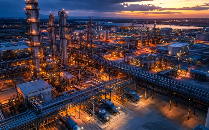
Χημικά και Πετροχημικά
Οι φυγοκεντρικές αντλίες, οι συμπιεστές, οι αναδευτήρες και οι κινητήρες ανάμειξης αντιπροσωπεύουν το μεγαλύτερο τμήμα μίας τελικής χρήσης. Οι κινητήρες αντιεκρηκτικής προστασίας (Ex d ή Ex e) είναι υποχρεωτικοί σε ταξινομημένες περιοχές Ζώνης 1 και Ζώνης 2. Η Korea Ever-Power's Κινητήρες με αντιεκρηκτική προστασία σειράς YB2 Καλύπτουν 0,55 έως 200 kW με πιστοποίηση Ex d IIB T4. |
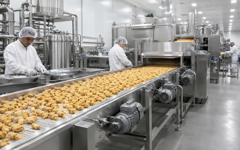
Επεξεργασία Τροφίμων και Ποτών
Τα συστήματα μεταφοράς, οι μηχανές πλήρωσης, οι γραμμές συσκευασίας και ο εξοπλισμός ανάμειξης απαιτούν κινητήρες που αντέχουν στην καθημερινή πλύση υψηλής πίεσης. Οι τριφασικοί κινητήρες από ανοξείδωτο χάλυβα με πιστοποίηση IP69K και λιπαντικά ποιότητας τροφίμων αποτελούν το πρότυπο για την υγιεινή κίνηση σε χώρους παραγωγής κρέατος, γαλακτοκομικών προϊόντων και ποτών. |
Μεταλλεία και Χύδην Υλικά
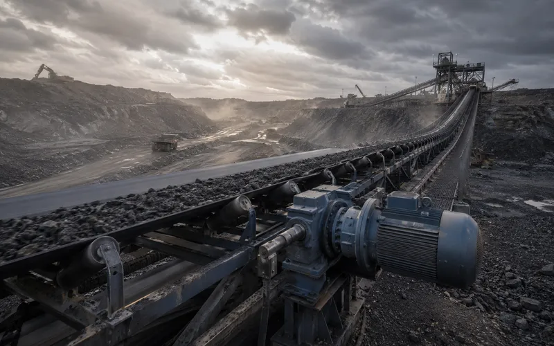
Οι μεταφορικοί ιμάντες μεγάλων αποστάσεων, οι κινητήρες θραυστήρων και οι κινητήρες σφαιρόμυλων θέτουν σοβαρές απαιτήσεις στη ροπή εκκίνησης του κινητήρα και τη θερμική χωρητικότητα. Οι κινητήρες υψηλής ροπής 6 και 8 πόλων, που συχνά συνδυάζονται με ελικοειδή ή κωνικά ελικοειδή κιβώτια ταχυτήτων, αποτελούν την τυπική λύση για φορτία επεξεργασίας ορυκτών υψηλής αδράνειας. |
Φυγοκεντρικοί ανεμιστήρες, αντλίες κυκλοφορίας, ανεμιστήρες πύργου ψύξης και μονάδες επεξεργασίας αέρα. Οι κινητήρες VFD μεταβλητής ταχύτητας εξοικονομούν ενέργεια από 30 έως 50 τοις εκατό σε σύγκριση με τη λειτουργία σταθερής ταχύτητας με μερικό φορτίο.
Οι μηχανές περιέλιξης, οι κινητήρες τυπογραφικών πιεστηρίων και οι κύλινδροι τάνυσης ιστού απαιτούν αθόρυβη λειτουργία και ακριβή έλεγχο ταχύτητας, κάτι που συνήθως επιτυγχάνεται με κινητήρες VFD και κινητήρες AC αντί για άμεση σύνδεση σταθερής ταχύτητας.
Υποβρύχιες αντλίες κίνησης, φυσητήρες αερισμού και εξοπλισμός αφυδάτωσης λάσπης. Απαιτούνται ανθεκτικά στη διάβρωση πλαίσια και υψηλές βαθμολογίες IP για εξωτερικές εγκαταστάσεις ή εγκαταστάσεις αντλιοστασίων κάτω από την επιφάνεια της γης.
Άξονες εργαλειομηχανών, υδραυλικά μηχανών χύτευσης με έγχυση, ρομποτικά σερβοσυστήματα κυψελών συγκόλλησης και κινητήρες πρέσας. Ο τετραπολικός κινητήρας στις 1.450 σ.α.λ. είναι η προεπιλεγμένη επιλογή για τους περισσότερους βοηθητικούς κινητήρες εργαλειομηχανών λόγω της ισορροπημένης αναλογίας ροπής προς μέγεθος.
8. Συχνές ερωτήσεις
Ψάχνετε για έναν τριφασικό επαγωγικό κινητήρα για την εφαρμογή σας;
Η Korea Ever-Power κατασκευάζει την πλήρη σειρά Y2 από 0,18 kW έως 200 kW σε διαμορφώσεις 2 πόλων, 4 πόλων, 6 πόλων και 8 πόλων, με προστασία IP44 έως IP69K και απόδοση IE3 ως στάνταρ.
Επεξεργασμένο από Cxm