VFD Inverter Duty Motors – YVF2 Variable Frequency Three-Phase Motor
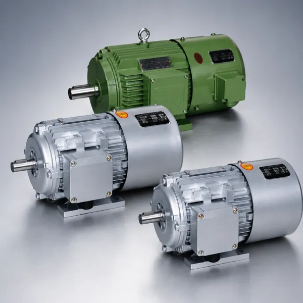
YVF/YVF2 Series Variable Frequency Motor Overview
The YVF2 series variable frequency three-phase asynchronous motor is developed from the Y2 series platform with specific design modifications for inverter-fed operation. Unlike standard induction motors that operate at a fixed speed determined by the supply frequency, VFD motors are designed to run at continuously variable speeds controlled by an external variable frequency drive (inverter). This combination of motor and VFD enables precise speed regulation, soft starting, energy savings on variable-torque loads, and process optimization across a wide range of industrial applications.
The primary engineering difference between a VFD motor and a standard three-phase motor lies in three areas: the insulation system is upgraded to H-class (180°C) with corona-resistant wire to withstand the high dV/dt voltage spikes produced by PWM inverter output; the cooling system uses an independently powered axial fan (IC416) instead of a shaft-mounted fan, ensuring constant airflow regardless of motor speed; and the electromagnetic design is optimized to minimize torque pulsation and audible noise under variable-frequency excitation.
Our factory currently produces YVF2 motors in 12 frame sizes from IEC 80 to 315, covering 23 power ratings from 0.55 kW to 315 kW. The constant-torque speed range is 5–50 Hz, and the constant-power range extends from 50 Hz up to 100 Hz, making these motors suitable for both low-speed high-torque and high-speed constant-power applications.
Technical Specifications
| Parameter | Specification |
|---|---|
| Motor Series | YVF2 (Inverter Duty, IE2/IE3 available) |
| Power Range | 0.55 kW – 315 kW (0.75 HP – 420 HP) |
| IEC Frame Sizes | 80M, 90S/L, 100L, 112M, 132S/M, 160M/L, 180M/L, 200L, 225S/M, 250M, 280S/M, 315S/M/L |
| Number of Poles | 4-pole standard (1500 rpm at 50Hz); 2-pole and 6-pole available on request |
| Rated Voltage | 380V (standard), 400V, 440V, 460V, 690V available |
| Base Frequency | 50Hz standard (60Hz available) |
| Constant-Torque Range | 5 Hz – 50 Hz (speed ratio 10:1) |
| Constant-Power Range | 50 Hz – 100 Hz |
| Insulation Class | Class H (180°C) with corona-resistant magnet wire |
| Protection Class | IP55 (dust-tight, water jet protected) |
| Cooling Method | IC416 (totally enclosed, independently ventilated by separate AC fan motor) |
| Cooling Fan Power Supply | Single-phase 220V/50Hz or three-phase 380V/50Hz (connected directly to mains, not VFD output) |
| Encoder Option | Incremental encoder 1024 PPR (pulses per revolution), 5V TTL or 12V line driver output |
| Insulation Voltage Rating | Withstands peak voltage ≥ 1,600V from PWM inverter output (dV/dt ≥ 1,000 V/µs) |
| Duty Rating | S1 (continuous), rated for 100% torque at all speeds within constant-torque range |
| Mounting | IM B3 (foot), IM B5 (flange), IM B35 (combined) |
| Housing Material | Aluminum alloy (frame 80–160), Cast iron (frame 160–315) |
| Vibration (Unloaded) | ≤ 1.8 mm/s (frame 80–132); ≤ 2.8 mm/s (frame 160–315) |
| Noise (Unloaded, at base frequency) | Frame 80: 73 dB(A); Frame 132: 80 dB(A); Frame 200: 92 dB(A); Frame 280: 99 dB(A) |
| VFD Compatibility | Compatible with all major VFD brands: ABB ACS, Siemens G120/S120, Danfoss FC, Yaskawa A1000, Delta VFD, Schneider ATV |
| Standards Compliance | JB/T 7118-2004, IEC 60034, GB/T 755, NEMA MG1 Part 31 (inverter-fed motors) |
Torque-Speed Characteristics
The following table shows the rated output power, rated torque, and matched VFD capacity for our 4-pole YVF2 series motors. The constant-torque range allows full rated torque from 5 Hz to 50 Hz. Above 50 Hz, the motor enters constant-power mode with torque decreasing inversely with speed.
| Frame Size | Rated Power (kW) | Rated Torque (N·m) | Matched VFD (kW) | Const-Torque Range (Hz) | Const-Power Range (Hz) |
|---|---|---|---|---|---|
| 80M | 0.55 – 0.75 | 3.5 – 4.7 | 0.75 – 1.5 | 5 – 50 | 50 – 100 |
| 90S/L | 1.1 – 1.5 | 7.0 – 9.5 | 1.5 – 2.2 | 5 – 50 | 50 – 100 |
| 100L | 2.2 – 3.0 | 14 – 19 | 3.0 – 4.0 | 5 – 50 | 50 – 100 |
| 132S/M | 5.5 – 7.5 | 35 – 47.7 | 7.5 – 11 | 5 – 50 | 50 – 100 |
| 160M/L | 11 – 15 | 70 – 95.5 | 15 – 18.5 | 5 – 50 | 50 – 100 |
| 180M/L | 18.5 – 22 | 117 – 140.9 | 22 – 30 | 5 – 50 | 50 – 100 |
| 200L | 30 | 190.9 | 37 | 5 – 50 | 50 – 100 |
| 225S/M | 37 – 45 | 235.5 – 286.4 | 45 – 55 | 5 – 50 | 50 – 100 |
| 250M | 55 | 350.1 | 75 | 3 – 50 | 50 – 100 |
| 280S/M | 75 – 90 | 447.7 – 572.9 | 90 – 110 | 3 – 50 | 50 – 100 |
Why Use a Dedicated VFD Motor Instead of a Standard Motor
While standard three-phase induction motors can be operated on a VFD for basic speed adjustment, there are measurable performance and reliability differences when using a purpose-built inverter-duty motor. The table below highlights the engineering reasons to specify a YVF2 motor for demanding variable-speed applications.
| Feature | Standard Motor on VFD | YVF2 Inverter-Duty Motor |
|---|---|---|
| Insulation System | F-class (155°C), standard wire | H-class (180°C), corona-resistant wire rated for ≥1,600V peak |
| Cooling at Low Speed | Shaft-mounted fan — airflow drops proportionally with speed | Independent fan runs at constant speed — full cooling at all motor speeds |
| Torque at Low Speed | Must be derated below 25 Hz (typically 60–70% torque at 10 Hz) | 100% rated torque from 5 Hz to 50 Hz — no derating required |
| Speed Feedback | Open-loop V/f control only | Closed-loop vector control with optional 1024 PPR encoder |
| Expected Winding Life | Reduced by 30–50% due to PWM voltage stress | Full rated winding life — insulation designed for inverter operation |
| Bearing Current Protection | None — risk of bearing fluting | Insulated bearing option (frame 160+) or shaft grounding ring |
Features and Engineering Advantages
Corona-Resistant Insulation System
All YVF2 stator windings use double-coated corona-resistant magnet wire with a rated impulse voltage withstand capability of 1,600V peak minimum. The wire insulation incorporates nano-filled enamel that resists partial discharge degradation caused by high-frequency PWM switching. Combined with VPI (vacuum pressure impregnation) treatment, this insulation system maintains its dielectric integrity for the full service life of the motor even under continuous inverter excitation.
Independent Forced-Ventilation Cooling (IC416)
A separate fan motor mounted on the NDE bracket provides constant airflow regardless of the main motor speed. This eliminates the thermal derating problem that occurs when a standard shaft-mounted fan slows down at low motor speeds. The cooling fan is powered directly from the mains supply (not from the VFD output), ensuring consistent cooling performance from standstill through maximum speed. The fan motor is typically rated at 30–80W depending on frame size.
Optional Encoder for Closed-Loop Control
An incremental encoder (1024 PPR, 5V TTL or 12V line driver) can be factory-installed on the NDE shaft extension. This provides precise speed feedback to the VFD for closed-loop vector control, enabling speed regulation accuracy of ±0.01% and torque response times under 10 ms. Encoder feedback is required for applications demanding precise speed synchronization, such as multi-axis winders, web handling systems, and CNC machine tool spindles.
Low Torque Ripple Design
The stator slot geometry and rotor bar skew angle are optimized specifically for variable-frequency excitation. This reduces electromagnetic torque pulsation at low frequencies, resulting in smoother shaft rotation without the cogging effect that can occur when standard motors run at speeds below 15 Hz. Smooth low-speed operation is critical for conveyor positioning, extruder screw drives, and precision coating applications.
Industry Applications
VFD motors paired with variable frequency drives offer significant advantages in energy savings, process control, and equipment protection across a wide range of industrial sectors:
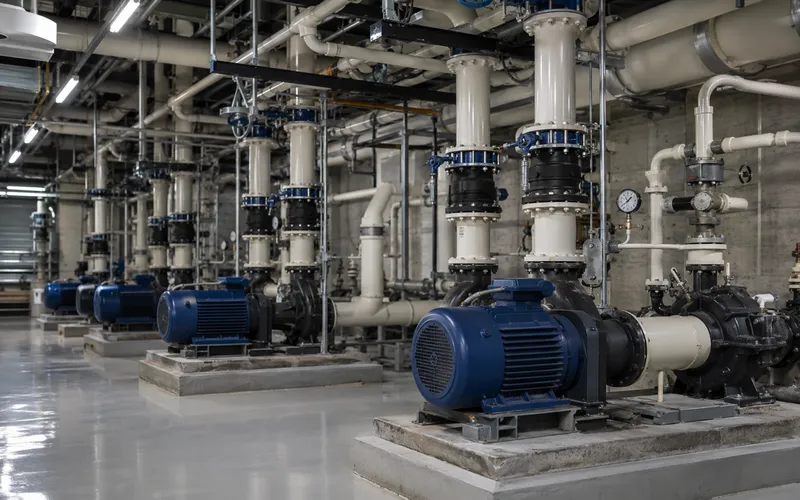
HVAC Fans and PumpsVariable-speed control of centrifugal fans and pumps reduces energy consumption by 30–60% compared to fixed-speed operation with throttle valves. The affinity laws mean power consumption drops with the cube of speed reduction. |
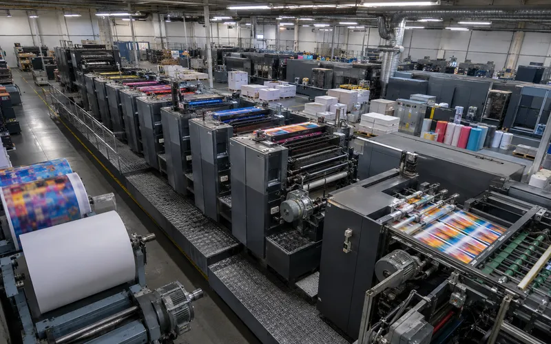
Printing and Web HandlingClosed-loop vector control with encoder feedback enables precise web tension regulation and line speed synchronization between multiple print stations, winders, and unwinders operating at coordinated speeds. |
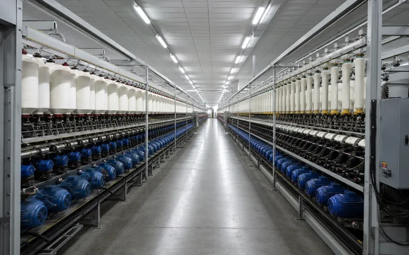
Textile and Wire DrawingVariable-speed spindle drives for spinning frames, drawing machines, and twisters. Speed adjustment allows processing of different fiber types and denier specifications without mechanical gear changes. |
Extruders and Plastics Processing
Screw speed directly controls output rate and melt quality. VFD motors provide smooth, vibration-free rotation from 10% to 100% of rated speed. Constant torque at low speeds is essential for high-viscosity polymer processing. Typical power range: 11–160 kW.
CNC Machine Tool Spindles
Milling, turning, and grinding machine spindle drives require wide speed range with constant power above base frequency. The 50–100 Hz constant-power range allows doubling the spindle speed for light finishing cuts, improving surface quality and cycle time.
Conveyors and Material Handling
Adjustable conveyor speed enables line balancing, gentle product handling, and accumulation zone control. Soft starting via VFD ramp eliminates belt slippage and reduces mechanical stress on couplings, bearings, and belt splices.
VFD Motor and Drive Pairing Guide
When selecting a VFD to pair with a YVF2 motor, the VFD rated output current must equal or exceed the motor rated current. For heavy-duty applications (frequent starts, high inertia loads, or operation with sustained overloads), select a VFD one size larger than the motor rating. The following table shows recommended VFD sizing:
| Motor Power (kW) | Motor Rated Current (A) | VFD Normal Duty (kW) | VFD Heavy Duty (kW) |
|---|---|---|---|
| 0.75 | 2.1 | 0.75 | 1.5 |
| 2.2 | 5.1 | 2.2 | 4.0 |
| 5.5 | 12.2 | 5.5 | 7.5 |
| 11 | 23.8 | 11 | 15 |
| 22 | 45.5 | 22 | 30 |
| 45 | 89.0 | 45 | 55 |
| 75 | 139.6 | 75 | 90 |
Installation and Wiring Notes
Connect the main motor power cables (U1, V1, W1) to the VFD output terminals (U, V, W). Use shielded motor cable with the shield grounded at both the VFD and motor ends to reduce electromagnetic interference. Cable length between VFD and motor should not exceed 50 meters without an output reactor or dV/dt filter.
Connect the independent cooling fan directly to the mains power supply through a separate circuit breaker or contactor. Do not connect the fan to the VFD output. The fan must run continuously whenever the motor is operating, including during low-speed operation.
If an encoder is installed, connect the encoder cable to the VFD PG (pulse generator) input card using shielded twisted-pair cable. Keep the encoder cable separated from power cables by at least 200 mm and cross at 90° angles where separation is not possible.
For motor cables longer than 30 meters, install a sine-wave filter or dV/dt reactor at the VFD output to limit voltage spikes at the motor terminals. This extends motor insulation life, especially for motors operating on 460V or 690V systems where reflected wave voltages can exceed 1,200V peak.
Frequently Asked Questions
What is a VFD motor and how is it different from a standard motor?
A VFD motor (also called an inverter-duty motor) is a three-phase induction motor specifically designed for operation with a variable frequency drive. It differs from a standard motor in three key areas: reinforced insulation to withstand PWM voltage spikes, an independent cooling fan that provides constant airflow at all speeds, and optimized electromagnetic design for smooth torque delivery across the entire speed range.
Can I use a standard three-phase motor with a VFD?
Yes, for basic applications with a limited speed range (typically 30–60 Hz) and moderate duty cycles. However, standard motors must be derated at low speeds due to reduced cooling capacity, and the insulation system may degrade faster under continuous inverter operation. For applications requiring operation below 20 Hz, frequent speed changes, or continuous low-speed duty, a dedicated VFD motor is recommended to avoid premature insulation failure.
What is the constant-torque speed range?
The constant-torque range is the frequency band within which the motor can deliver 100% of its rated torque without thermal derating. For our YVF2 series, this range is 5 Hz to 50 Hz (base frequency). Below 5 Hz, torque capability begins to decrease. Above 50 Hz, the motor enters constant-power mode where torque decreases inversely with speed while power output remains constant up to 100 Hz.
Do I need an encoder for my VFD application?
An encoder is not required for most variable-torque applications such as fans, pumps, and blowers where open-loop V/f or sensorless vector control provides adequate speed regulation (typically ±0.5–1% accuracy). An encoder is recommended for applications requiring precise speed control (±0.01%), high dynamic torque response, zero-speed holding torque, or multi-axis speed synchronization. Common encoder-required applications include winders, unwinders, CNC spindles, and multi-section printing presses.
How much energy can a VFD save on pump and fan applications?
For centrifugal pumps and fans following the affinity laws, a 20% reduction in speed results in approximately 50% reduction in power consumption. In typical HVAC and water pumping installations, VFD control saves 30–60% of energy compared to fixed-speed operation with throttle valves or dampers. The payback period for a VFD investment is usually 6 to 18 months depending on operating hours and electricity rates.
What is bearing fluting and how do VFD motors prevent it?
Bearing fluting is a pattern of electrical discharge damage on bearing raceways caused by common-mode currents generated by VFD switching. Over time, these micro-pits create visible grooves (flutes) in the bearing races, leading to increased noise, vibration, and premature bearing failure. Our YVF2 motors in frame sizes 160 and above are available with an insulated non-drive end bearing and/or a shaft grounding brush ring to divert these currents away from the bearing surfaces.
Which VFD brands are compatible with your YVF2 motors?
Our YVF2 motors are compatible with all standard voltage-source PWM inverters. We have verified compatibility with ABB ACS580/ACS880, Siemens G120/S120, Danfoss FC302, Yaskawa A1000/GA700, Delta VFD-C2000, Schneider ATV630/ATV930, Fuji FRENIC, and Mitsubishi FR-A800. Motor nameplate data is provided in a format suitable for direct entry into VFD auto-tune routines.
Can a VFD motor also be combined with an electromagnetic brake?
Yes. Our YVF2EJ series combines the inverter-duty motor design with an integrated electromagnetic brake. This combination is used for crane travel drives, servo positioning, and machine tool axis drives where both variable speed and fail-safe holding brake functions are required. The brake coil must be wired to a separate power supply independent of the VFD output.
What cable length is allowed between the VFD and the motor?
Without any output filtering, the maximum recommended cable length between VFD and motor is 50 meters for 380V systems and 30 meters for 460V systems. Beyond these distances, reflected voltage waves at the motor terminals can exceed the insulation withstand capability. For longer cable runs, install a dV/dt reactor or sine-wave filter at the VFD output. Our YVF2 motors with H-class insulation provide an additional safety margin compared to standard motors in this regard.
What is the lead time for VFD motors with encoder?
Standard YVF2 motors without encoder in common frame sizes ship within 10–18 business days. Motors with factory-installed encoder require 18–25 business days to allow for encoder mounting, wiring, and testing. Contact our team for current availability and pricing for your specific motor and encoder configuration.
Customer Experiences
We installed YVF2-160M-4 motors on 12 chilled water pumps across our commercial building portfolio. Combined with ABB ACS580 drives, the VFD system reduced annual pump energy consumption by 42% compared to the previous fixed-speed setup with throttle valve control. The payback period was under 11 months. The independent cooling fans have been running without issue for 20 months straight.
Daniel W., Building Services Manager
Property Management Group, London, United Kingdom
Our plastics extrusion line uses YVF2-200L-4 motors with 1024 PPR encoders for closed-loop screw speed control. The speed stability is excellent — we measured ±0.02% speed variation at 15 Hz under fluctuating load conditions. This level of control eliminated the melt quality issues we experienced with our previous open-loop VFD motor setup.
Kenji T., Process Engineer
Plastics Extrusion Manufacturer, Osaka, Japan
We needed 8 VFD motors for a paper mill winder section upgrade. The Ever-Power team helped us size the motors for constant-power operation above base frequency to match our production speed requirements. All motors were delivered with Siemens-compatible encoder feedback and pre-tested motor parameters on the nameplate for direct VFD auto-tune entry. Integration time was cut in half compared to our usual commissioning process.
Lars E., Automation Manager
Paper Mill, Gothenburg, Sweden
Important Technical Note
The torque and speed characteristics listed on this page assume operation with a standard PWM voltage-source inverter at rated voltage and base frequency. Actual motor performance under VFD control depends on the VFD control method (V/f, sensorless vector, or closed-loop vector), VFD carrier frequency setting, motor cable length, and the accuracy of motor parameter entry in the VFD setup. For applications requiring guaranteed performance specifications, provide your complete application parameters including load torque curve, speed range, and duty cycle. Our engineering team will perform a detailed motor-drive matching calculation and provide verified performance data. All specifications conform to JB/T 7118-2004, IEC 60034, and NEMA MG1 Part 31 standards.
Need a VFD Motor Quotation?
Tell us your motor power, speed range, VFD brand, and whether you need an encoder. We will provide a matched motor-drive recommendation with technical datasheet and pricing within 24 hours.
Additional information
| Editor | Cxm |
|---|