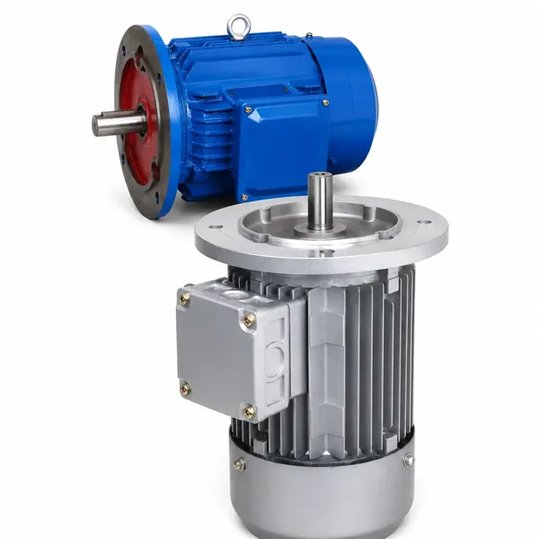
1. Why the Nameplate Is the Primary Data Source
IEC 60034-1 (Rotating Electrical Machines — Rating and Performance) specifies the data that must appear on every AC motor nameplate. The nameplate values are the rated conditions at which the motor meets all its performance guarantees simultaneously. Running the motor outside the nameplate operating range — higher current, lower voltage, excessive ambient temperature — does not necessarily cause immediate failure, but it reduces insulation life, bearing life, and long-term reliability in proportion to the degree and duration of the exceedance.
2. Power, Voltage, and Current
The shaft mechanical output power at rated conditions. This is what the motor delivers to the load — not the electrical power consumed. Electrical input power (kW consumed from supply) equals rated output divided by efficiency. A motor nameplate showing 15 kW at 92.5% efficiency consumes 15 ÷ 0.925 = 16.2 kW from the supply at full rated load.
The supply voltage at which the motor is designed to operate, and whether it should be connected in star (Y) or delta (△) for that voltage. A nameplate showing “380 V Y” means connect in star on a 380 V supply. “220/380 V △/Y” means delta for 220 V or star for 380 V. Operating above or below rated voltage by more than ±5% degrades motor performance and shortens service life.
The line current the motor draws from the supply when producing rated output power at rated voltage and frequency. This value is used to: set the overload protection relay (typically 100 to 105% of this value); size the supply cables (cable must carry this current continuously); select the contactor current rating; and calculate reactive power demand for power factor correction planning.
Three-phase motor input power formula: P‑input (kW) = √3 × V (kV) × I (A) × cosφ — where V is the line-to-line voltage and I is the rated line current from the nameplate. You can verify the nameplate current is consistent with the stated power and power factor using this formula.
3. Speed, Frequency, and Slip
The rated speed shown on the nameplate is the actual rotor speed at full load — always slightly below the synchronous speed determined by pole count and supply frequency. This difference is the slip.
| Poles | Synchronous Speed (50 Hz) | Typical Nameplate Speed | Slip at Full Load | Typical Applications |
|---|---|---|---|---|
| 2 | 3,000 rpm | 2,850–2,900 rpm | 1.7–5% | Centrifugal fans, turboblowers, high-speed pumps |
| 4 | 1,500 rpm | 1,420–1,460 rpm | 2.7–5.3% | General purpose: pumps, conveyors, compressors, machine tools |
| 6 | 1,000 rpm | 940–970 rpm | 3–6% | Agitators, large fans, slow speed conveyors, kilns |
| 8 | 750 rpm | 700–730 rpm | 4–6.7% | Very slow loads, large agitators, grain handling, direct drives |
The rated speed on the nameplate allows you to calculate the shaft torque at rated power: T (N·m) = 9,550 × P (kW) ÷ n (rpm). For a 4 kW motor at 1,440 rpm, rated torque = 9,550 × 4 ÷ 1,440 = 26.5 N·m. This torque value is needed to specify the coupling between the motor and driven machine.
4. Efficiency Class and Power Factor
The efficiency value on the nameplate is the ratio of shaft output power to electrical input power at rated load, measured at rated voltage and frequency. The IE class (IE2, IE3, IE4) indicates which international efficiency tier the motor achieves. These two items together tell you the energy cost of operating the motor: annual energy cost = (rated kW ÷ η) × operating hours × electricity rate (£/kWh or $/kWh).
Annual cost = (7.5 ÷ 0.898) × 4,000 × 0.13 = $4,344/yr
The ratio of active power (kW) to apparent power (kVA). A motor with cos φ of 0.86 draws more apparent current than its active power consumption suggests: apparent current = active current ÷ cos φ. This matters for cable sizing (cables carry apparent current, not just active power current) and for facilities that pay reactive power tariffs on industrial supply contracts. The nameplate power factor is measured at full rated load; at 50% load it typically falls to 0.65 to 0.75, and below 25% load can drop below 0.5.
5. IP Rating, Insulation Class, and Duty Type
The two digits of the IP code (IEC 60529) indicate solid particle and water ingress protection. The first digit (0–6) indicates dust protection: 5 = dust-protected, 6 = dust-tight. The second digit (0–9K) indicates water protection: 4 = splash, 5 = water jets, 6 = powerful jets, 7 = temporary immersion, 8 = continuous immersion, 9K = high-pressure hot water jets. The IP code determines where the motor can be installed: IP44 for clean indoor use, IP55 for general industrial, IP65 for washdown areas, IP69K for food and pharmaceutical high-pressure washdown.
The insulation class defines the maximum permissible winding temperature. Class B = 130°C, Class F = 155°C, Class H = 180°C. Korea Ever-Power Y2 series motors use Class F insulation with temperature rise limited to 80 K (Class B rise), giving a thermal reserve of 25 K above the ambient-plus-rise sum that extends insulation life significantly. The insulation class constrains the maximum ambient temperature at which the motor can operate at full load — at ambient above 40°C, a motor with Class F insulation and Class B rise must be derated.
IEC 60034-1 defines nine duty types (S1 to S9) describing how the motor’s load varies over time. S1 means the motor runs continuously at constant load long enough to reach thermal equilibrium — this is the most common and the most demanding duty from a thermal perspective. S3 (intermittent periodic duty with a stated cyclic duty factor) allows a motor to carry a higher nameplate power because it has rest periods for cooling. A motor rated for S3 duty at 40% CDF must not be used in S1 continuous duty without derating.
6. Frame Size and Mounting Code
The IEC frame size designation (e.g. 132S, 160M, 200L) encodes the shaft height and the stator stack length. The number is the shaft height in mm measured from the motor base to the shaft centre. The letter suffix (S = short, M = medium, L = long) indicates the stack length within that shaft height, determining the active copper and iron volume and therefore the power output at each shaft height.
The IEC mounting code (IM designation) on the nameplate specifies how the motor is installed: foot, flange, vertical, or combined. IM B3 = foot horizontal, IM B5 = flange horizontal, IM B35 = foot plus flange. For three-phase motors in IEC frames, the shaft height and foot hole spacing are standardised by IEC 72-1, ensuring mechanical interchangeability between motors of the same frame designation from different manufacturers.
| Frame | Shaft Height | Typical kW Range |
|---|---|---|
| 71 | 71 mm | 0.18–0.55 |
| 80 | 80 mm | 0.37–0.75 |
| 90 | 90 mm | 0.75–2.2 |
| 100 | 100 mm | 2.2–3.0 |
| 112 | 112 mm | 3.0–5.5 |
| 132 | 132 mm | 5.5–11 |
| 160 | 160 mm | 11–18.5 |
| 180–315 | 180–315 mm | 22–200+ |
7. Worked Example: Reading a Full Nameplate
The following example shows how to extract practical engineering values from a typical Korea Ever-Power Y2 series nameplate:
What This Nameplate Tells You


8. Frequently Asked Questions
Edited by Cxm