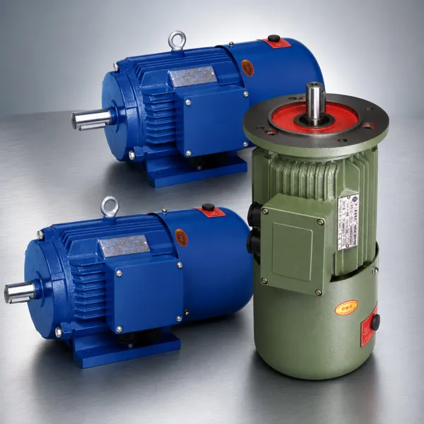
1. How a Brake Motor Works
A brake motor integrates a three-phase induction motor with an electromagnetic brake into a single compact unit. The brake is mounted on the non-drive end of the motor shaft, inside a protective cover that is part of the motor enclosure. The motor and brake share the same terminal box, simplifying electrical installation — the main three-phase supply connects the motor winding in the standard way, and a separate DC supply (typically 24 V DC, derived from a rectifier module in the motor’s terminal box or from the control panel) energises the brake coil.
The critical operational principle is fail-safe design: the brake engages mechanically by spring force and is released electrically by the DC electromagnet. This means that a power failure, an emergency stop, or any interruption of the supply causes the brake to engage automatically without any control signal — the load is secured as the default state, not as an active control action.
Three-phase supply energises motor winding simultaneously with DC supply to brake coil. Electromagnet overcomes spring force and releases armature disc from brake disc, allowing shaft to rotate. Motor accelerates to running speed within 1 to 3 seconds.
Motor drives the load at rated speed. Brake coil remains energised, holding the brake open. Brake disc rotates freely with the shaft — there is no contact between rotating brake disc and stationary brake plate during normal running.
Three-phase supply and DC brake coil both de-energise simultaneously. Spring force immediately presses the armature disc against the friction brake disc. Friction braking decelerates the shaft to standstill within 0.1 to 0.5 seconds depending on brake torque and load inertia.
2. Spring-Applied Electromagnetic Brake Principle
The electromagnetic brake inside a Y2EJ brake motor consists of five key components, all mounted concentrically on the motor shaft extension at the NDE end:
Splined to the motor shaft and rotates with it. Made from friction material with high and stable friction coefficient across the operating temperature range. The brake disc is the wear element in the brake assembly — its thickness decreases with each braking event, and the air gap adjustment must compensate as wear accumulates.
A steel disc that slides axially on the guide pins but does not rotate. When the brake is engaged, the compression springs push the armature disc against the rotating brake disc, creating the clamping force that generates braking torque. When the electromagnet is energised, it pulls the armature disc away from the brake disc against the spring force, creating the air gap that allows free rotation.
Multiple compression springs around the brake circumference provide the clamping force when the electromagnet is de-energised. Spring force determines the static holding torque of the brake. Springs are sized to provide brake torque at a specified multiple of the motor rated torque — typically 1.5 to 2.0 times rated motor torque to hold loads on inclines or prevent drift from external forces.
A DC electromagnet coil mounted in the brake housing. When energised by DC voltage (typically 24 V DC in Korea Ever-Power Y2EJ series, derived by a half-wave or full-wave rectifier from the motor’s three-phase supply), it creates a magnetic field that attracts the armature disc away from the brake disc against the spring force, creating the release air gap of 0.1 to 0.3 mm.
A mechanical lever on the brake housing that can release the brake manually without DC power. The manual release is used for maintenance positioning, load lowering during power failure, and initial commissioning. The manual release must be disengaged and the lever returned to its normal position before the motor resumes production operation.
3. Brake Torque and Stop Time Selection
The two key brake selection parameters are the required brake torque and the required stop time. These two parameters are linked through the deceleration rate and the load inertia, so they must be specified together rather than independently.
| Application | Required Stop Time | Typical Brake Torque Ratio | Notes |
|---|---|---|---|
| Man-riding hoist | < 0.15 s | 3.0–4.0 × motor rated torque | Safety regulation requirement; oversized brake for emergency |
| Material hoist / crane | < 0.3 s | 1.5–2.5 × motor rated torque | Load holding after positioning; fast stop to prevent swing |
| Conveyor (positioning) | < 0.5 s | 1.5–2.0 × motor rated torque | Precise stop position for product transfer; prevent drift |
| Packaging machine | < 0.3 s | 1.5–2.0 × motor rated torque | Tooling positioning; prevent product jam; safety guard interlock |
| Holding (no motion needed) | Static hold only | 1.2–1.5 × motor rated torque | Inclined conveyor; vertical axis; prevent back-drive |
4. Duty Cycle and Thermal Rating of the Brake
Each braking event dissipates kinetic energy as heat in the brake disc friction surface. The brake’s thermal capacity limits the maximum number of braking events per hour before the brake disc overheats and friction properties degrade. This is the brake duty cycle limit, and it is independent of the motor duty cycle.
Each braking event from rated speed to standstill dissipates kinetic energy E = ½ × J × ω². For a 4 kW motor at 1,450 rpm with J = 0.04 kg·m², E = 0.5 × 0.04 × (151.8)² = 461 J. If the motor starts and stops 60 times per hour, the brake dissipates 461 × 60 = 27,660 J/hour = 7.7 W average. This must stay within the brake’s rated average thermal dissipation capacity.
The brake disc wears at a rate proportional to the braking energy per event and inversely proportional to the disc material wear resistance. Korea Ever-Power Y2EJ series brakes are designed for a minimum of 2 million braking operations from rated speed at rated braking torque before the disc requires replacement, assuming normal ambient temperatures and infrequent emergency braking. The air gap between armature and brake disc increases as the disc wears; the brake must be adjusted when the air gap exceeds the maximum specified value (typically 0.5 to 0.8 mm, depending on brake size).
Korea Ever-Power Y2EJ series brakes are rated for up to 240 braking operations per hour (operating class AC3 per IEC 60947) at rated braking torque and rated motor speed. This limit applies to continuous repetitive cycling applications such as packaging machines and short-cycle conveyors. Applications exceeding 240 braking operations per hour require a brake motor with a higher operating class rating, available as a special specification on request.
5. Korea Ever-Power Y2EJ Series Brake Motor
The Korea Ever-Power Y2EJ series is a three-phase induction motor with an integral spring-applied, electrically released electromagnetic brake. It is designed as a direct replacement for standard Y2 series motors in applications requiring controlled stopping — the Y2EJ shares the same IEC frame dimensions and terminal box layout as the Y2, allowing it to be installed in the same footprint without any modification to the machine structure. The brake motor product range covers 0.18 to 45 kW in 2-pole (2,850 rpm), 4-pole (1,450 rpm), 6-pole (960 rpm), and 8-pole (720 rpm) configurations.
The brake coil is energised at 24 V DC, supplied by a half-wave rectifier module installed inside the motor’s terminal box. The rectifier is fed from two phases of the main three-phase supply, so the brake releases simultaneously with the motor when the main contactor closes — no separate brake control circuit is required. This integrated design simplifies panel wiring and eliminates the timing relay or PLC output that would otherwise be needed to coordinate motor start and brake release.
| Power range | 0.18 – 45 kW |
| Poles | 2P / 4P / 6P / 8P |
| Brake type | Spring-applied, DC released |
| Brake voltage | 24 V DC (integral rectifier) |
| Typical stop time | 0.1 – 0.5 s |
| Brake torque | 1.5–2.5 × rated motor torque |
| Manual release | Standard on all models |
| Protection | IP54 (motor + brake) |
| Insulation | Class F |
6. Application Areas for Brake Motors

Hoists and Cranes
Chain and wire rope hoists, overhead travelling cranes, and jib cranes are the primary application for brake motors. The integral brake holds the suspended load stationary whenever the hoist is not actively moving, preventing drift or drift under gravity. The Y2EJ 4-pole series at 0.37 to 5.5 kW covers the full range of workshop hoists and industrial cranes. Safety regulations for man-riding hoists require a specific brake performance standard — Korea Ever-Power can advise on the appropriate brake torque rating for safety-classified lifting applications. |
Packaging and Processing Machines
Filling machines, form-fill-seal packaging lines, labelling machines, and carton erectors all require motors that stop at a repeatable position when the cycle completes and hold that position until the next cycle starts. A brake motor achieves this without encoder feedback or servo control — the brake engages on every cycle stop, maintaining the tooling position accurately. The Y2EJ 4-pole and 6-pole series at 0.18 to 2.2 kW covers most packaging machine drive requirements. |
Inclined belt and chain conveyors carrying heavy loads require a brake motor to prevent reverse running under gravity when the motor stops. The Y2EJ brake prevents load rollback without any external mechanical backstop.
Vertical axis drives on drilling machines, boring mills, and lathes use brake motors to hold the spindle head or cross-slide in position while the workpiece is changed, preventing gravity-driven drift that would damage the tooling or workpiece.
Industrial roller doors, sectional doors, and automated gate drives use Y2EJ brake motors to hold the door or gate at any intermediate position and to ensure the door stops immediately if the safety edge sensor is triggered.
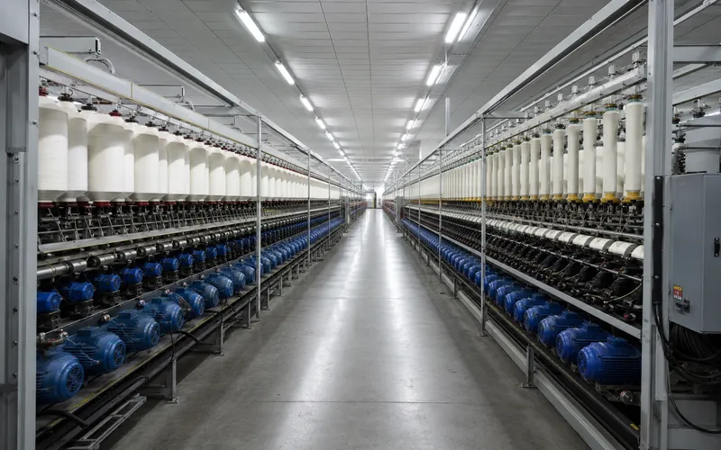
Warping machines, winding machines, and tentering frame drives require fast, repeatable stopping at every pattern change or end-of-roll to maintain yarn tension and web position. Brake motors replace mechanical clutch-brake combinations with fewer maintenance points.

7. Frequently Asked Questions
Edited by Cxm