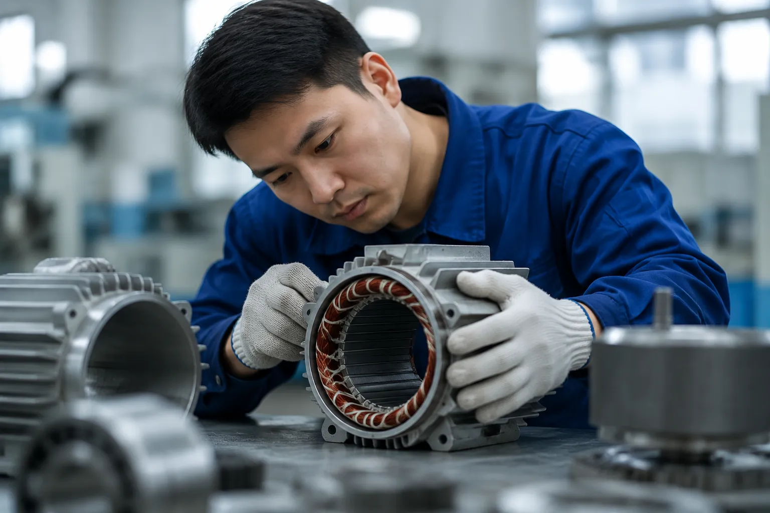
1. Why Planned Maintenance Reduces Total Cost of Ownership
The total cost of owning an industrial electric motor over its service life is dominated by energy cost (typically 97 to 99 percent of total lifetime cost for continuously running motors) and failure-related costs (unplanned downtime, emergency replacement, production loss). The motor purchase price accounts for less than 2 percent of total lifetime cost in most applications.
Electric motor maintenance programmes work on two distinct mechanisms. First, they extend service life by preventing the progressive damage that accumulates from contaminated bearings, degraded insulation, and blocked cooling — reducing the frequency of early failure. Second, they give maintenance teams advance warning of developing faults, allowing motors to be replaced on a planned schedule during scheduled production downtime rather than as an emergency during production hours. Emergency motor replacements typically cost 4 to 10 times more than planned replacements when production loss cost is included.
2. Daily and Weekly Visual Checks
Daily and weekly electric motor maintenance checks require no tools and no motor isolation — they are performed during normal production operation by operations or maintenance staff as part of a routine equipment walk-around. Despite their simplicity, they catch a significant proportion of developing problems before they cause a production stop.
Walk past each motor during normal operation and listen for changes from the baseline sound. Grinding or rumbling from bearings, increased humming from electrical issues, or rattling from loose fan cover or terminal box screws are all audible before they appear in any instrument reading. Log any change from normal baseline sound immediately and schedule investigation.
Briefly touch the motor frame (not the fan cover — this can be hotter than the frame) to confirm it is warm but not excessively hot. A Class F motor in normal S1 duty at 40°C ambient will have a frame surface temperature of approximately 55 to 75°C — warm to the touch but holdable for 1 to 2 seconds. A frame too hot to touch briefly (above approximately 80°C surface) indicates overloading, blocked cooling, or elevated ambient temperature requiring investigation.
Check for: visible grease or oil leakage around the shaft seal (indicates seal wear); corrosion on frame, end shields, or fasteners (indicates moisture ingress or chemical exposure requiring immediate investigation in food and chemical plant areas); dust or debris accumulation on cooling fins restricting airflow; loose or missing hold-down bolt nuts; coupling guard in place and secure; terminal box cover sealed and screws tight.
Briefly place a hand flat on the motor frame while it is running. Normal vibration should be barely perceptible. Vibration clearly felt by touch, or vibration visible in the mounting structure, indicates a developing mechanical issue — misalignment, unbalanced load, or bearing deterioration. Log the observation and schedule a formal vibration measurement at the next available opportunity.
3. Monthly Checks: Current, Vibration, and Temperature
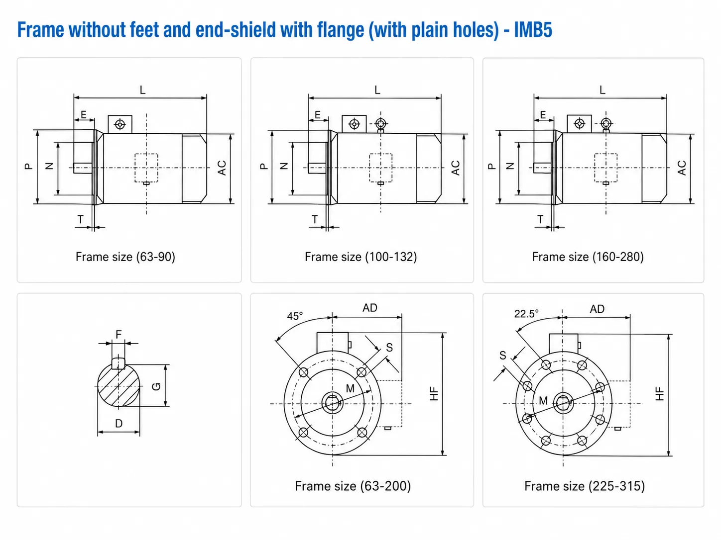
Measure all three phase currents with a clamp meter under the motor’s normal operating load. Record the values and compare with the nameplate full-load current and with previous monthly readings. Acceptable current balance: all three phases within 5 percent of each other. Current above nameplate indicates overload. A current imbalance above 5 percent indicates supply voltage imbalance or a developing winding fault and requires further investigation. Trending current readings over successive months reveals progressive changes before they reach fault level.
Measure the bearing housing temperature at both drive-end and non-drive-end bearing positions using a contact or infrared thermometer. Compare with the baseline temperature established during commissioning. A bearing temperature rise of 10 K above the established baseline at the same ambient temperature and load indicates developing bearing deterioration (contamination, loss of lubrication, or beginning of fatigue). Bearing temperature above 90°C at the housing surface requires immediate investigation regardless of the trend.
Measure vibration velocity (mm/s RMS) at the bearing housing in three axes: horizontal, vertical, and axial. Compare with IEC 60034-14 Grade A limit of 2.8 mm/s RMS for standard motors in frames 56 to 400. Levels above 4.5 mm/s indicate a developing problem requiring investigation. Trending vibration over successive months reveals alignment deterioration, foundation loosening, or bearing wear progression. Monthly vibration trending is the most effective condition monitoring technique for early fault detection in electric motor installations.
4. Annual Maintenance: Insulation, Bearings, Terminals
Annual electric motor maintenance requires a planned shutdown period — typically during scheduled plant maintenance or equipment overhaul intervals. The motor should be isolated, locked out, and allowed to cool before any work begins. The following tasks should be completed at every annual maintenance interval:
| Task | Method | Acceptance Criterion | Action If Failed |
|---|---|---|---|
| Insulation resistance test | 500 V DC megohmmeter, phase-to-earth | ≥ 1 MΩ at 20°C | Dry out; retest. If still low, inspect and rewind. |
| Winding resistance balance | Milliohmmeter on each phase | All phases within ±2% | Investigate for turn-to-turn short or open circuit. |
| Cooling fin cleaning | Compressed air or vacuum | All passages clear of debris | Manual cleaning with brush if debris is packed. |
| Terminal tightness check | Torque wrench to IEC 60999 spec | No looseness; no discolouration | Re-torque; replace discoloured terminals. |
| Bearing assessment | Listen and feel for roughness; check grease | Smooth rotation; fresh grease | Regrease if due; replace if rough. |
| Earth continuity check | Low-resistance ohmmeter, frame to PE | < 0.5 Ω frame to PE terminal | Check earth lead and connection; clean contact point. |
| Alignment re-check | Dial indicator or laser alignment | Within coupling manufacturer spec | Re-align with shims; check foundation bolts. |
5. Bearing Replacement Intervals and Procedure
Bearings are the primary wear component in squirrel-cage AC induction motors. Bearing selection and replacement intervals depend on the operating speed, radial load, ambient temperature, and lubrication condition. Korea Ever-Power Y2 series motors in frames up to 160L use sealed-for-life deep-groove ball bearings that require no regreasing and should be replaced at the intervals below. Frame sizes 180M and above use re-greasable bearings with grease nipples.
| Operating Condition | Replace At |
|---|---|
| Normal load, 40°C ambient, continuous | 20,000–30,000 h |
| High radial load (belt or chain drive) | 10,000–15,000 h |
| High ambient temperature (>50°C) | 10,000–20,000 h |
| Frequent starts / stops (>60/hour) | 8,000–12,000 h |
| VFD-driven (bearing current risk) | 5,000–10,000 h without protection |
Bearing replacement note: always replace both DE and NDE bearings at the same time, even if only one shows signs of wear. Mixing a new bearing with a worn one creates unequal radial stiffness and will accelerate wear on the new bearing. Use only bearings of the exact specification shown on the motor data plate or Korea Ever-Power spare parts list.
6. Winding Re-varnish and Rewind Decision Criteria
When an annual insulation resistance test returns a value below 1 MΩ after the motor has been fully dried, or when visual inspection reveals carbonised winding insulation or cracked coil sections, the motor winding requires either re-varnishing (if only surface contamination has occurred) or a full rewind.
Vacuum pressure impregnation (VPI) with polyester or epoxy resin is appropriate when: insulation resistance is below 1 MΩ due to surface moisture absorption or light contamination (the winding structure is mechanically intact); visual inspection shows no charred, cracked, or physically damaged coil sections; and the winding resistance balance is within ±2% (indicating no turn-to-turn short circuits). VPI restores surface insulation integrity and typically recovers insulation resistance to above 100 MΩ on a clean, mechanically intact winding.
A full rewind is required when: winding resistance is unbalanced by more than 2% between phases (turn-to-turn short circuit confirmed); there is visible charring, carbonisation, or physical damage to coil sections; insulation resistance remains below 1 MΩ after thorough drying and VPI treatment; or the motor has failed electrically (phase-to-phase or phase-to-earth short circuit). For motors below 11 kW, compare rewind cost against the price of a new Korea Ever-Power Y2 series replacement — new motor replacement is often more cost-effective below this power level.
7. Electric Motor Maintenance Schedule Reference
| Task | Daily | Weekly | Monthly | Annual | Per Hours |
|---|---|---|---|---|---|
| Sound / noise check | ✓ | — | |||
| Frame temperature touch check | ✓ | — | |||
| Visual inspection, vibration by touch | ✓ | — | |||
| Phase current measurement (all 3 phases) | ✓ | — | |||
| Bearing temperature (infrared / contact) | ✓ | — | |||
| Vibration velocity measurement | ✓ | — | |||
| Insulation resistance measurement | ✓ | — | |||
| Winding resistance balance | ✓ | — | |||
| Terminal tightness and cooling fin cleaning | ✓ | — | |||
| Alignment re-check | ✓ | — | |||
| Bearing regreasing (frame 180 and above) | 4,000–8,000 h | ||||
| Bearing replacement (frame up to 160L) | 20,000–30,000 h |

8. Frequently Asked Questions
Edited by Cxm