2. Hovedkomponenter og deres funktioner
3. Korthårs- vs. sårrotortyper
4. Forklaring af de vigtigste elektriske specifikationer
5. Effektivitetsklasser: IE1, IE2, IE3, IE4
6. IP- og isoleringsklassevurderinger
7. Typiske anvendelser efter branche
8. Ofte stillede spørgsmål
1. Hvordan en trefaset induktionsmotor fungerer
En trefaset induktionsmotor fungerer efter et princip, der blev opdaget af Nikola Tesla i 1887: Når tre sinusformede vekselspændinger adskilt af 120 grader påføres tre sæt statorviklinger arrangeret omkring en cylindrisk ramme, genererer de et roterende magnetfelt inde i motoren. Dette roterende felt roterer med en synkron hastighed, hvilket er lig med 60 gange forsyningsfrekvensen divideret med antallet af polpar (for eksempel ved 50 Hz med 2 poler: 3.000 o/min; med 4 poler: 1.500 o/min).
Det roterende magnetfelt skærer gennem rotorens ledere. Fordi rotorlederne er lukkede kredsløb (kortsluttede stænger i et kortslutningsdesign), inducerer den skiftende magnetiske flux en spænding i dem ved hjælp af Faradays lov om elektromagnetisk induktion. Denne inducerede spænding driver strømme gennem rotorstængerne. Disse rotorstrømme interagerer med det roterende magnetfelt for at producere en kraft på rotorlederne, og rotoren begynder at dreje i feltets retning - men altid lidt langsommere end den synkrone hastighed.
Denne hastighedsforskel mellem det synkrone felt og den faktiske rotorhastighed kaldes glideSlip er afgørende: Hvis rotoren kørte med præcis synkron hastighed, ville der ikke være nogen relativ bevægelse mellem felt- og rotorledere, ingen induceret spænding, ingen rotorstrøm og intet drejningsmoment. Ved fuld belastning varierer typiske slipværdier fra 1 til 5 procent for industrielle kortslutnings-trefasede induktionsmotorer.
Det smukke ved dette design er, at der ikke er nogen elektrisk forbindelse mellem statorforsyningen og rotoren. Energi overføres udelukkende via magnetisk induktion over et luftgab på 0,2 til 0,5 mm. Dette eliminerer børster, slæberinge og kommutatorer, hvilket gør kortslutningsmotoren med trefaset induktion til den enkleste og mest pålidelige roterende maskine i industriel brug.
2. Hovedkomponenter og deres funktioner
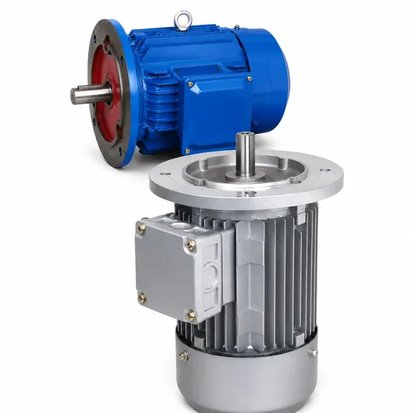
Alle trefasede induktionsmotorer deler den samme grundlæggende arkitektur uanset effekt eller producent. Forståelse af hver dels funktioner hjælper med motorvalg, installation, fejlfinding og vedligeholdelsesplanlægning.
Den stationære ydre enhed. Den består af en lamineret siliciumstålkerne pakket ind i motorrammen, med tre sæt kobberviklinger indsat i slidser omkring den indre omkreds. Trefaseforsyningen forbindes til disse viklinger og genererer det roterende magnetfelt. Statorlamineringer reducerer hvirvelstrømstab; tyndere lamineringer betyder lavere jerntab og højere effektivitet.
Den roterende indre samling. I en kortslutningsmotor er rotorkernen også lamineret siliciumstål med aluminium- eller kobberstænger støbt eller indsat i rotorslidser. Stængerne er kortsluttet i begge ender af ledende enderinge, der danner en burform. Rotorakslen overfører mekanisk drejningsmoment til den drevne belastning. Der kræves ingen ekstern elektrisk forbindelse til rotoren.
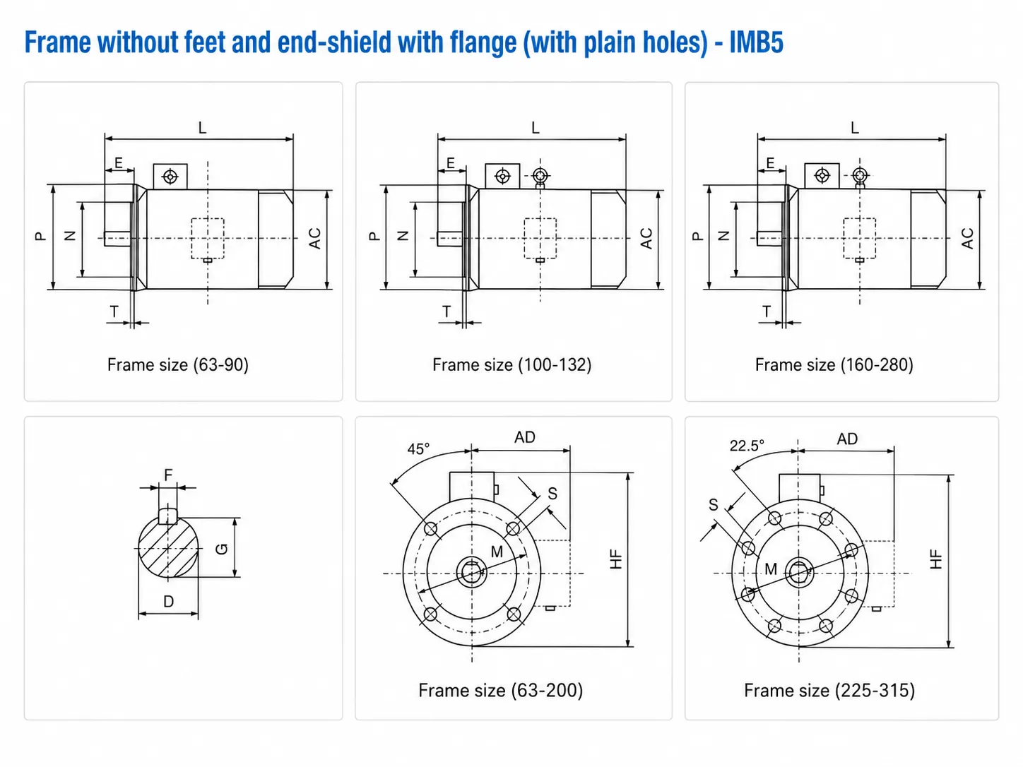
Støbejerns- eller aluminiumsrammen huser statoren og yder strukturel støtte, varmeafledning gennem eksterne køleribber og beskyttelse af de indvendige viklinger. Endeskjolde (endeplader) lukker hver ende af rammen og bærer lejerne, der understøtter rotorakslen. Rammens dimensioner følger IEC 72-1-standarderne, så motorer fra forskellige producenter er mekanisk udskiftelige med samme rammebetegnelse.
Lejer understøtter rotorakslen og opretholder det præcise luftgab mellem rotor og stator. Sporkuglelejer er standard til rammer op til 250 mm. Større rammer bruger en kombination af et rulleleje i drivenden (til at håndtere radial belastning fra rem- eller kædedrev) og et kugleleje i ikke-drivenden. Lejernes levetid er typisk 20.000 til 30.000 driftstimer ved nominel belastning og normal omgivelsestemperatur.
En ventilator af plastik eller metal er monteret på den ikke-drevne ende af akslen, inde i et ventilatordæksel med luftindtags- og udløbsåbninger. Når motoren kører, trækker ventilatoren køleluft hen over de udvendige rammelameller og fører varme væk, der genereres af kobbertab i viklinger og jerntab i kernen. Denne IC411-anordning (fuldstændig lukket ventilatorkølet) er den globale standard for industrielle trefasede induktionsmotorer.
En støbt kasse oven på eller ved siden af motorrammen, der indeholder klembrættet til tilslutning af forsyningskablerne. Standard trefasede induktionsmotorer har seks terminaler (U1, V1, W1, U2, V2, W2), der muliggør stjerne- eller trekantforbindelse. Klemmekassens position kan normalt drejes til fire positioner (øverst, venstre, højre, modsatte drivende) for at tilpasse den til kabelindføringsretningen. Klemmekassens IP-klassificering matcher eller overstiger stellets klassificering.
3. Korthårs- vs. sårrotortyper
Trefasemotorer findes i to rotorkonfigurationer. Valget mellem dem afhænger af startkrav, behov for hastighedsregulering og belastningsegenskaber.
| Ejendom | Korthårsrotor | Viklet rotor (slip-ring) |
|---|---|---|
| Rotorkonstruktion | Aluminium- eller kobberstænger, kortsluttede endringe | Trefasede viklede spoler, forbundet via slæberinge til ekstern modstand |
| Startstrøm | Høj (5–8 × nominel strøm ved direkte start) | Reduceret (ekstern modstand begrænser indkoblingsstrøm) |
| Startmoment | God (1,8–3,0 × nominelt drejningsmoment) | Fremragende (op til 2,5-3,5 × nominelt drejningsmoment med fuld ekstern modstand) |
| Hastighedskontrol | Kræver VFD til variabel hastighed | Begrænset hastighedsområde via ekstern rotormodstand (ineffektiv) |
| Opretholdelse | Minimal (kun lejer) | Almindelig (børster, slæberinge, eksterne modstandsbanker) |
| Koste | Sænke | Højere (motor + ekstern modstandsudstyr) |
| Typiske anvendelser | Pumper, ventilatorer, kompressorer, transportbånd — langt de fleste industrielle drev | Store kraner, taljer, højinerti-kværne (ældre anvendelser) |
Branchebemærkning: I moderne installationer er viklede rotormotorer i vid udstrækning blevet erstattet af kortslutningsmotorer parret med frekvensomformere (VFD'er). VFD'er giver mere præcis hastighedskontrol, bedre energieffektivitet og lavere vedligeholdelse end viklede rotormodstandsstartere. Nye installationer af viklede rotortyper er sjældne ud over ældre udskiftningssituationer.

4. Forklaring af de vigtigste elektriske specifikationer
Hvert motornavneskilt har et sæt nominelle værdier, der definerer motorens normale driftspunkt. Disse tal danner grundlag for motorvalg, indstillinger af beskyttelsesrelæer, kabeldimensionering og beregning af energiomkostninger. Den komplette vejledning til aflæsning af disse værdier findes i produktsektion for trefaset motor.
Akseludgangseffekten ved fuld belastning. Dette er den effekt, motoren leverer til det drevne udstyr, ikke den elektriske effekt, der trækkes fra forsyningen. Elektrisk indgangseffekt = akseleffekt divideret med virkningsgraden. En 15 kW motor med 92% virkningsgrad trækker 16,3 kW fra forsyningen ved fuld belastning.
Forsyningsspændingen, som motoren er designet til at fungere ved. Den globale standard for forsyningsspænding er 380 V (IEC-regioner) eller 460 V (Nordamerika). Motorer med dobbeltspænding (f.eks. 220 V/380 V) kan tilsluttes i delta for 220 V eller stjerne for 380 V. Drift over eller under nominel spænding med mere end 5 procent forårsager overophedning og momentreduktion.
Netstrømmen, der trækkes fra forsyningen ved nominel spænding og fuld belastning. Brug denne værdi til at dimensionere forsyningskabler, sikringer og motorbeskyttelsesrelæer. Startstrømmen (Ist) er typisk 5 til 8 gange nominelstrømmen for en kortslutningsmotor ved direkte start og varer 1 til 10 sekunder, indtil motoren når driftshastighed.
Akselens rotationshastighed ved fuld belastning, som er lidt under den synkrone hastighed på grund af slip. Ved 50 Hz er typiske nominelle hastigheder: 2-polet = 2.900 o/min (synkron 3.000 o/min), 4-polet = 1.450 o/min (synkron 1.500 o/min), 6-polet = 960 o/min (synkron 1.000 o/min), 8-polet = 720 o/min (synkron 750 o/min). Den 4-polede motor med 1.450 o/min er den mest anvendte konfiguration i industriel praksis.
Akseludgangseffekt som en procentdel af elektrisk indgangseffekt ved fuld belastning. Moderne IE3-motorer opnår en effektivitet på 88 til 96 procent afhængigt af effektklassificeringen, med højere effektivitet ved større stelstørrelser. Effektiviteten falder kraftigt under 50 procent belastning, hvilket gør korrekt motordimensionering afgørende for energiomkostningsstyring.
Forholdet mellem aktiv effekt (kW) og tilsyneladende effekt (kVA). Disse motorer er induktive belastninger med effektfaktorer, der typisk spænder fra 0,75 til 0,90 ved fuld belastning. Lav effektfaktor betyder højere forsyningsstrøm for den samme udgangseffekt, hvilket øger kabeltab og potentielle reaktive effekttariffer. Effektfaktorkorrektionskondensatorer eller VFD'er med aktiv frontend kan kompensere.
5. Effektivitetsklasser: IE1, IE2, IE3, IE4
Standarden 60034-30-1 fra Den Internationale Elektrotekniske Kommission (IEC) definerer fire effektivitetsklasser for AC-asynkronmotorer med én hastighed. Disse klasser fastsætter minimumseffektivitetsniveauer ved nominel belastning, nominel spænding og nominel frekvens, hvilket gør det nemt at sammenligne motorer fra forskellige producenter og verificere overholdelse af lovgivningen.
| IE-klasse | Navn | Eksempel på virkningsgrad (4 kW, 4-polet) | Reguleringsstatus |
|---|---|---|---|
| IE1 | Standard effektivitet | ~82.6% | Ikke længere tilladt i EU / mange markeder for salg af nye biler |
| IE2 | Høj effektivitet | ~84.7% | Minimum for mange eksportmarkeder; under IE3-kravet i EU over 0,75 kW |
| IE3 | Premium effektivitet | ~87.0% | Obligatorisk minimum i EU, Storbritannien og mange andre markeder siden 2021 (0,75-200 kW) |
| IE4 | Super Premium Effektivitet | ~89.0% | Fås på forespørgsel; obligatorisk i nogle regioner for specifikke effektområder fra 2023 og fremefter |
Forskellen i effektivitet mellem IE2 og IE3 kan virke lille procentvis, men den kumulative energibesparelse over en motors levetid er betydelig. En 15 kW trefaset induktionsmotor, der kører 4.000 timer om året ved 90 procent belastning, forbruger cirka 54.000 kWh/år. Forskellen mellem IE2's (91.0%) og IE3's (92.1%) effektivitet ved dette driftspunkt sparer cirka 650 kWh om året - hvilket ved typiske industrielle elpriser (120 til 180 USD/MWh) repræsenterer 78 til 117 USD årligt for en enkelt motor.
De VFD-invertermotorer I Korea er Ever-Powers YVF2-serie designet til at opretholde IE3-effektivitetsniveauer, selv når de drives på tværs af hele VFD-frekvensområdet, ved hjælp af forstærket isolering til at modstå PWM-skifttransienter, der ville forringe standardmotorviklinger ved delvis hastighed.
6. IP- og isoleringsklassevurderinger
IP-beskyttelsesklasser (IEC 60529)
IP-koden (Ingress Protection) består af to cifre. Det første ciffer (0 til 6) angiver beskyttelse mod faste partikler, herunder støv. Det andet ciffer (0 til 9K) angiver beskyttelse mod vandindtrængning. Højere tal betyder bedre beskyttelse.
| IP-klassificering | Beskyttelsesniveau | Typisk brug |
|---|---|---|
| IP44 | Beskyttet mod partikler over 1 mm, vandsprøjt fra alle retninger | Indendørs, rene miljøer |
| IP54 | Støvbeskyttet, vandsprøjt fra alle retninger | De fleste industrielle miljøer |
| IP55 | Støvbeskyttet, vandstråler fra alle retninger | Udendørs eller våde procesområder |
| IP65 | Støvtætte vandstråler fra alle retninger | Vaskeområder, fødevareforarbejdning |
| IP69K | Støvtætte højtryksvandstråler (80 bar, 80°C) | Afvaskning af fødevarer, lægemidler og mejeriprodukter |
Koreas evige magt Motorer i rustfrit stål med IP69K (BXG-serien) har den højeste beskyttelsesklassificering og er designet til daglig højtryksspuling i fødevare- og farmaceutiske faciliteter.
Isolationsklasser (IEC 60034-1)
Isolationsklassen definerer den maksimale temperatur, som motorviklingens isolering kan modstå kontinuerligt uden forringelse. Den faktiske viklingstemperatur er summen af omgivelsestemperaturen og temperaturstigningen forårsaget af motortab.
| Klasse | Maks. viklingstemperatur | Almindelig brug |
|---|---|---|
| Klasse B | 130°C | Ældre; sjældent brugt i nye motorer |
| Klasse F | 155°C | Standard for de fleste industrielle trefasede motorer i dag. Korea Ever-Power Y2/YB2/Y2EJ bruger klasse F med en temperaturstigningsgrænse på klasse B — hvilket giver en termisk reserve på 25 K. |
| Klasse H | 180°C | Spulmotorer (BXG-serien), VFD-driftsmotorer, installationer i tropisk klima |
| Klasse C | 220°C | Omgivelser med høj omgivelsestemperatur; specialspecifikation |
Korea Ever-Powers standardpraksis: Klasse F-isolering normeret til 155 °C med en temperaturstigning i viklingen begrænset til 80 K (klasse B-grænse). Dette giver en termisk reserve på 25 K over standarden, hvilket forlænger isoleringens levetid betydeligt under normale omgivelsesforhold.
7. Typiske anvendelser efter branche
Trefasemotorer er arbejdshesten inden for industriel kraftomdannelse. Deres kombination af enkelhed, pålidelighed og tilpasningsevne gør dem velegnede til næsten enhver roterende belastning inden for fremstilling, forarbejdning og infrastruktur.

Kemisk og petrokemisk
Centrifugalpumper, kompressorer, omrørere og blandemotorer repræsenterer det største enkeltstående slutbrugersegment. Eksplosionssikre motorer (Ex d eller Ex e) er obligatoriske i klassificerede zone 1- og zone 2-områder. Korea Ever-Powers YB2-seriens eksplosionssikre motorer dækker 0,55 til 200 kW i Ex d IIB T4-certificering. |
Fødevare- og drikkevareforarbejdning
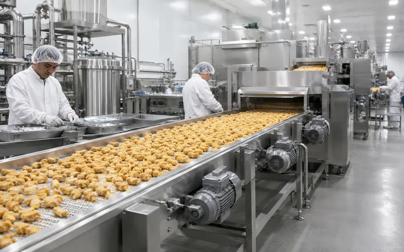
Transportbåndssystemer, påfyldningsmaskiner, pakkelinjer og blandeudstyr kræver motorer, der kan tåle daglig højtryksrensning. IP69K-klassificerede trefasede motorer i rustfrit stål med fødevaregodkendte smøremidler er standarden for hygiejniske områdedrev i kød-, mejeri- og drikkevareproduktion. |
Minedrift og bulkmaterialer
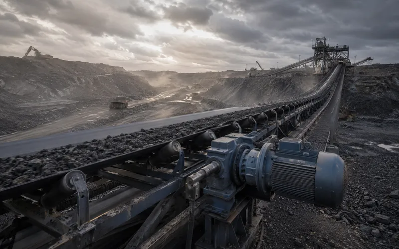
Langdistancebåndtransportører, knuserdrev og kuglemølledrev stiller store krav til motorens startmoment og termiske kapacitet. Højmoment 6-polede og 8-polede motorer, ofte parret med spiralformede eller koniske spiralformede gearkasser, er standardløsningen til mineralforarbejdningsbelastninger med høj inerti. |
Centrifugalventilatorer, cirkulationspumper, køletårnsventilatorer og luftbehandlingsenheder. VFD-motorer med variabel hastighed sparer 30 til 50 procent energi i forhold til drift med fast hastighed ved delvis belastning.
Viklemaskiner, trykpressedrev og banespændingsruller kræver støjsvag drift og præcis hastighedskontrol, hvilket typisk opnås med VFD-motorer og vekselstrømsdrev i stedet for direkte online-forbindelse med fast hastighed.
Dykpumpedrev, luftningsblæsere og slamafvandingsudstyr. Korrosionsbestandige rammer og høje IP-klassificeringer er påkrævet til udendørs eller underjordiske pumpestationsinstallationer.
Maskinværktøjsspindler, hydraulik til sprøjtestøbemaskiner, robotsvejsecelle-servosystemer og pressedrev. 4-polet motor ved 1.450 o/min er standardvalget for de fleste maskinværktøjshjælpedrev på grund af dets afbalancerede moment-til-størrelse-forhold.
8. Ofte stillede spørgsmål
Leder du efter en trefaset induktionsmotor til din anvendelse?
Korea Ever-Power fremstiller hele Y2-serien fra 0,18 kW til 200 kW i 2-polede, 4-polede, 6-polede og 8-polede konfigurationer med IP44 til IP69K-beskyttelse og IE3-effektivitet som standard.
Redigeret af Cxm