2. Pourquoi les moteurs standard tombent en panne sur un variateur de fréquence
3. Comparaison des circuits intégrés IC416 et IC411 : Refroidissement à basse vitesse
4. Isolation de classe H pour les pics de tension des variateurs de fréquence
5. Protection contre les surintensités des roulements
6. Spécifications YVF2 pour le CVC
7. Applications CVC
8. Foire aux questions
1. Économies d'énergie : L'intérêt des variateurs de fréquence pour les entraînements de ventilateurs et de pompes de systèmes de chauffage, ventilation et climatisation
Dans les bâtiments commerciaux et industriels, les ventilateurs et les pompes à eau glacée des systèmes de chauffage, ventilation et climatisation (CVC) sont généralement conçus pour répondre aux pics de charge, c'est-à-dire la journée la plus chaude de l'année ou la charge maximale du bâtiment occupé. Pendant 70 à 90 % des heures de fonctionnement, la demande réelle est nettement inférieure à ce pic. Pourtant, un moteur à vitesse fixe équipé d'un registre ou d'une vanne fonctionne à pleine puissance, gaspillant ainsi la capacité excédentaire. La régulation de vitesse par variateur de fréquence (VFD) élimine ce gaspillage en adaptant la vitesse du ventilateur ou de la pompe à la demande réelle.
Charge moyenne : 75% en crête
Consommation annuelle : 22 × 8 000 = 176 000 kWh
Coût annuel à $0,13/kWh = $22,880
Puissance moyenne : 22 × (0,85)³ = 13,5 kW
Consommation annuelle : 13,5 × 8 000 = 108 000 kWh
Coût annuel = $14 040 — économie de $8 840/an
Cet exemple illustre pourquoi la régulation de vitesse par variateur de fréquence (VFD) des ventilateurs et pompes de systèmes de chauffage, ventilation et climatisation (CVC) est généralement amortie en 6 mois à 2 ans, ce qui en fait l'un des investissements les plus rentables en matière d'efficacité énergétique pour les installations techniques du bâtiment. L'élément clé est d'associer le variateur de fréquence à un moteur YVF2 à variateur de fréquence, et non à un moteur Y2 standard, afin de garantir un fonctionnement fiable et durable.
2. Pourquoi les moteurs standard tombent en panne sur les variateurs de fréquence
Un moteur Y2 standard (IC411 autoventilé, isolation de classe F) connecté directement à un variateur de fréquence sans protection spécifique au moteur subira trois mécanismes de défaillance qui ne se produisent pas sur une alimentation sinusoïdale à fréquence fixe :
La tension de sortie d'un variateur de fréquence est modulée en largeur d'impulsion (PWM) et présente des pics de tension de commutation de 1 000 à 1 600 V (selon la longueur du câble et la fréquence de commutation du variateur), se répétant à une fréquence porteuse de 2 à 16 kHz. L'isolation des enroulements de classe F standard, conçue pour une alimentation sinusoïdale, se dégrade rapidement sous l'effet de pics de tension haute fréquence répétés. Les décharges partielles dans l'isolation des enroulements érodent progressivement l'isolation des conducteurs, provoquant des courts-circuits entre spires en 2 à 4 ans de fonctionnement du variateur sans une isolation moteur conforme aux spécifications.
Les moteurs IC411 standard utilisent un ventilateur monté sur l'arbre pour refroidir le stator et l'enroulement ; le débit d'air de refroidissement est proportionnel à la vitesse de l'arbre. À 25 Hz (50 TP3T de la vitesse nominale), le ventilateur ne fournit qu'environ 25 TP3T du débit d'air de refroidissement maximal. Cependant, à 25 Hz, le moteur produit toujours son couple nominal et donc environ 50 TP3T de sa puissance nominale, ce qui génère une chaleur importante que le ventilateur ne peut dissiper correctement. La température de l'enroulement dépasse la limite de la classe F, accélérant le vieillissement de l'isolation d'un facteur 2 pour chaque tranche de 10 K de dépassement (règle de Montsinger).
La commutation PWM des variateurs de fréquence crée un couplage capacitif entre les enroulements du stator et l'arbre du rotor, induisant une tension de mode commun sur ce dernier. Cette tension se décharge à travers les roulements du moteur (le chemin de moindre résistance vers la masse), provoquant un usinage par électroérosion (EDM) à haute fréquence des bagues et des billes. L'endommagement des roulements par ce courant engendre des motifs de givrage et de cannelures caractéristiques sur la surface des bagues, ce qui entraîne une augmentation des vibrations et une défaillance des roulements dans un délai de 6 à 18 mois pour les roulements standard non protégés fonctionnant avec des variateurs de fréquence à haute fréquence porteuse.
3. Comparaison des circuits intégrés IC416 et IC411 : Refroidissement à basse vitesse
La norme IEC 60034-6 définit les désignations des circuits de refroidissement des moteurs. Le circuit IC411 est un circuit de refroidissement standard à ventilation naturelle : le moteur se refroidit grâce à un ventilateur monté sur son arbre. Le circuit IC416 est un circuit de refroidissement à ventilation forcée : un moteur de soufflerie indépendant assure un flux d'air de refroidissement constant, quelle que soit la vitesse du moteur principal.
| Propriété | IC411 (Norme Y2) | IC416 (Série YVF2) |
|---|---|---|
| entraînement du ventilateur de refroidissement | Montage sur arbre (dépendant de la vitesse) | Moteur de soufflerie indépendant (constant) |
| Refroidissement à 25 Hz (vitesse 50%) | ~25% de débit d'air nominal | 100% de débit d'air nominal |
| Refroidissement à 5 Hz (vitesse 10%) | ~2% de débit d'air nominal — critique | 100% de débit d'air nominal |
| Couple nominal à basse vitesse | Réduire la fréquence en dessous de 30 Hz | Couple nominal maximal de 0 à la fréquence nominale |
| Couple de maintien statique (0 Hz) | Pas de refroidissement — ne convient pas | Refroidissement complet — maintien statique possible |
| adéquation du variateur de fréquence | Déconseillé en dessous de 50 Hz en continu | Conçu pour un fonctionnement avec variateur de fréquence de 0 à 120 Hz |
Pour les variateurs de fréquence des ventilateurs de systèmes de chauffage, ventilation et climatisation (CVC) fonctionnant régulièrement à une fréquence inférieure à 40 Hz (80% de la vitesse nominale) – plage de fonctionnement normale de la plupart des ventilateurs de centrales de traitement d'air et de tours de refroidissement à variateur de fréquence en dehors des périodes de forte charge – le refroidissement forcé IC416 est indispensable. Il constitue une condition essentielle à un fonctionnement sûr et fiable sur le long terme.
4. Isolation de classe H pour les pics de tension des variateurs de fréquence
La série YVF2 utilise une isolation d'enroulement de classe H (température maximale continue de 180 °C) avec une formulation adaptée aux variateurs de fréquence, offrant une résistance accrue aux décharges partielles. L'isolation de classe H du YVF2 offre deux niveaux de protection supplémentaires par rapport à l'isolation de classe F d'un moteur Y2 standard.
L'isolation de classe H pour variateurs de fréquence du YVF2 est formulée avec une rigidité diélectrique et une tension d'amorçage de décharge partielle supérieures à celles de l'isolation standard de classe F. Elle est conçue pour supporter des pics de tension répétitifs jusqu'à 1 600 V crête (dV/dt jusqu'à 5 000 V/µs) sans dégradation progressive de l'isolation, ce qui correspond aux caractéristiques de sortie des variateurs de fréquence modernes à IGBT fonctionnant avec des câbles jusqu'à environ 50 m sans filtrage de sortie supplémentaire.
Même avec le refroidissement forcé IC416, le fonctionnement d'un moteur à bas régime et à couple maximal génère plus de chaleur par unité de puissance de sortie qu'à régime nominal. La réserve thermique de 25 K de la classe H par rapport à la classe F signifie que l'enroulement YVF2 fonctionne à une fraction inférieure de sa limite thermique dans les mêmes conditions de fonctionnement, prolongeant ainsi la durée de vie de l'isolation conformément à la règle de Montsinger.
| Propriété | Classe F | Classe H |
|---|---|---|
| Température maximale | 155°C | 180°C |
| Réserve thermique* | 15 K | 40 K |
| Durée de vie relative à une température ambiante de 40 °C | 1× | 8× |
| Calibre de service VFD | Standard | Fonctionnement VFD |
5. Protection contre les surintensités des roulements
La série YVF2 protège les roulements des variateurs de fréquence contre les dommages causés par les courants de fuite à la terre grâce à une combinaison de choix des roulements, d'isolation et de conception de la mise à la terre. L'intensité du courant de fuite dépend de la taille du bâti moteur, de la fréquence porteuse du variateur et de la longueur du câble. Korea Ever-Power applique les mesures de protection suivantes dans la série YVF2 :
Pour les moteurs YVF2 de taille 180M et supérieure, le palier côté opposé à la transmission (NDE) est monté dans un logement isolé qui interrompt le circuit électrique entre l'arbre, le palier et le bâti. Le courant de palier est ainsi contraint de trouver un chemin alternatif vers la terre, n'empruntant pas les surfaces de palier, ce qui protège le palier côté transmission de la majeure partie du courant de circulation.
Une bague de mise à la terre conductrice en microfibre assure un chemin de faible impédance pour la décharge à la terre de la tension d'arbre en mode commun, sans passer par le palier. Recommandée pour les moteurs YVF2 de plus de 11 kW avec variateurs de fréquence à fréquence porteuse supérieure à 4 kHz, ou pour les installations avec de longs câbles moteur (plus de 30 m). Disponible en option chez Korea Ever-Power.
Un filtre dV/dt en sortie du variateur de fréquence (VFD) réduit la vitesse de montée en tension des impulsions PWM, limitant ainsi la surtension de crête aux bornes du moteur. Pour les câbles reliant le moteur au VFD d'une longueur supérieure à 50 m, un filtre dV/dt réduit la tension de crête aux bornes du moteur en dessous de la limite d'isolation YVF2, quelle que soit la fréquence de commutation du VFD. Korea Ever-Power recommande l'utilisation de filtres côté VFD pour les installations de ventilateurs de climatisation avec de longs trajets de câbles entre les panneaux VFD centraux et les centrales de traitement d'air (CTA) distantes.
6. Spécifications YVF2 pour les applications CVC
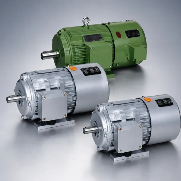
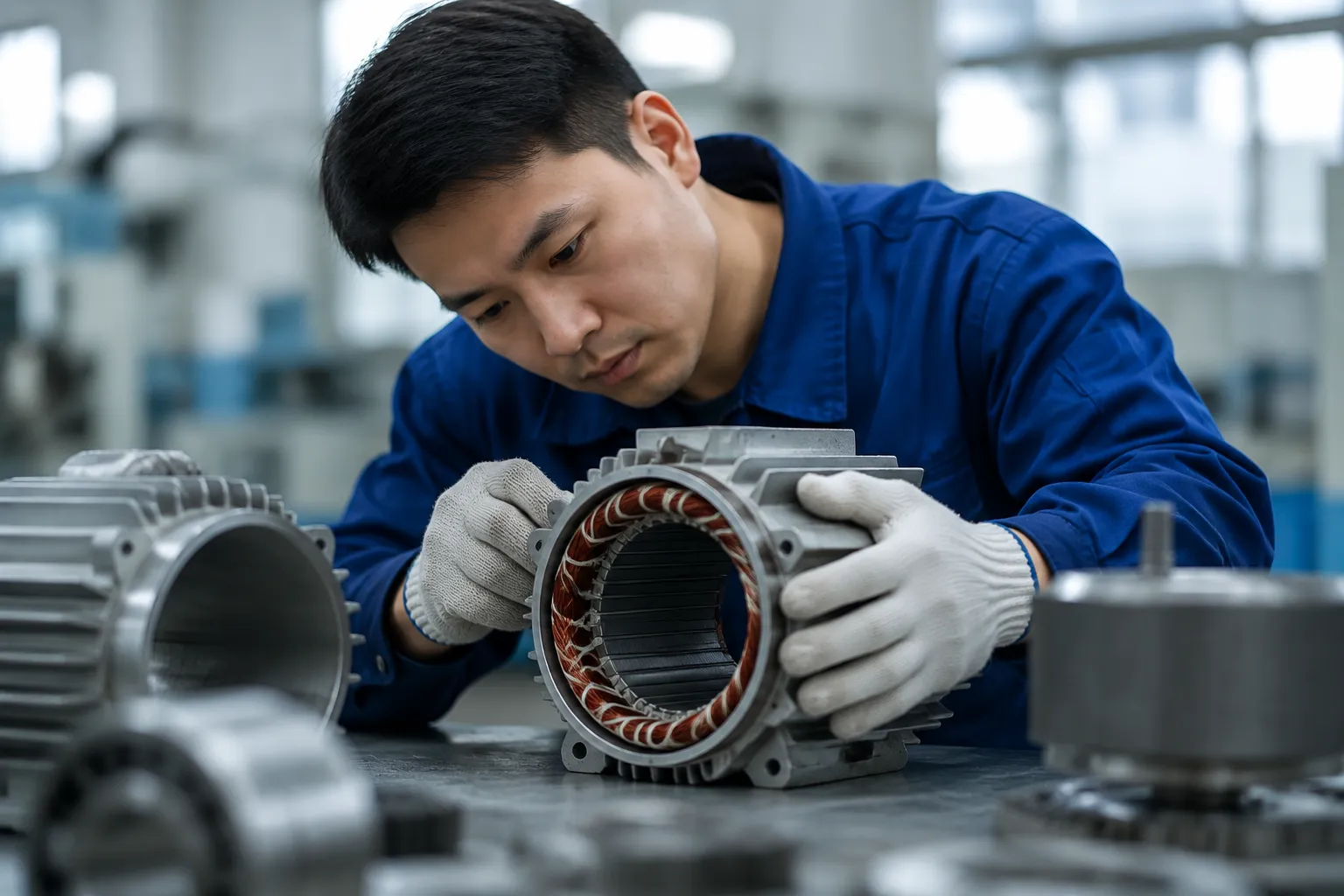
La série YVF2 d'Ever-Power (Corée) est un moteur spécialement conçu pour les variateurs de fréquence dans les systèmes CVC et industriels. Le YVF2 est disponible en plusieurs versions. section produits moteurs pour variateurs de fréquence Disponibles dans une gamme de puissance de 0,75 à 200 kW, en configurations à 2 et 4 pôles. La configuration à 4 pôles (1 450 tr/min) est la norme pour les ventilateurs de centrales de traitement d'air, les ventilateurs de tours de refroidissement et les pompes à eau glacée ; la configuration à 2 pôles (2 900 tr/min) est utilisée pour les ventilateurs centrifuges à grande vitesse et les pompes de process conçues pour un fonctionnement à 2 900 tr/min.
| Gamme de puissance | 0,75–200 kW |
| Refroidissement | Ventilation forcée IC416 |
| Isolation | Classe H, service VFD |
| Plage de vitesses | Alimentation VFD 0–120 Hz |
| Protection | norme IP54 |
| thermistances PTC | Standard — connexion à l'entrée PTC du variateur de fréquence |
| Capacité de pic de tension | Tension de crête jusqu'à 1 600 V |
| Pôles | 2P (2 900 tr/min) / 4P (1 450 tr/min) |
7. Applications CVC
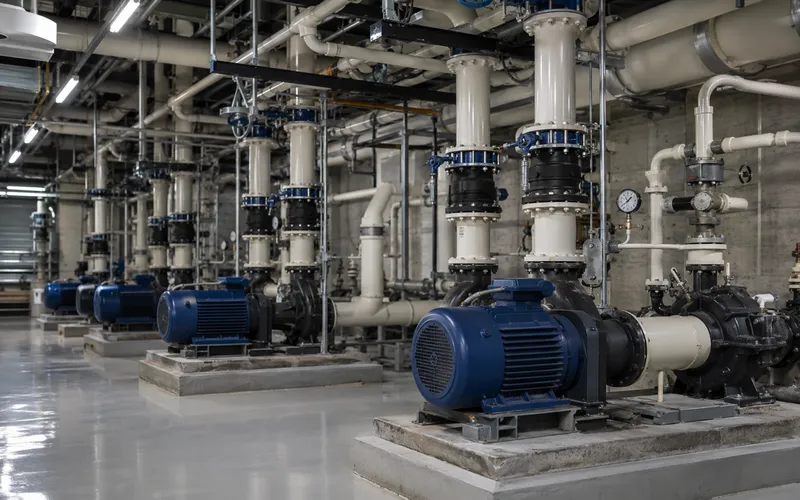
Pompes à eau glacée et à eau de condensation
Dans la plupart des bâtiments commerciaux, les pompes à eau glacée primaires et secondaires des systèmes de climatisation centralisés représentent le principal poste de consommation énergétique. Le variateur de fréquence YVF2 à 4 pôles (7,5 à 75 kW), associé à un système de gestion technique du bâtiment (GTB) piloté par un variateur de fréquence, assure une régulation du débit primaire variable (VPF), réduisant ainsi la consommation énergétique des pompes de 40 à 60 % par rapport aux systèmes à volume constant. Le variateur module la vitesse des pompes afin de maintenir la pression différentielle de consigne dans le réseau de distribution, même lorsque la position des vannes de zone varie en fonction de la charge. |
Ventilateurs d'alimentation et de reprise des unités de traitement d'air (UTA)
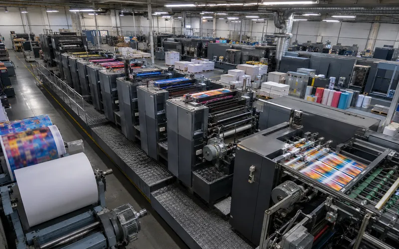
Les ventilateurs d'insufflation et de reprise des grandes centrales de traitement d'air (CTA) desservant les bureaux, les hôpitaux, les centres de données et les installations industrielles constituent la principale application des moteurs YVF2 en CVC. Ces moteurs de 7,5 à 90 kW sont pilotés par variateur de fréquence (VFD) depuis un système de gestion technique du bâtiment (GTB) ou un contrôleur CVC autonome afin de maintenir la température de l'air soufflé et la pression statique dans les gaines aux valeurs de consigne. Les systèmes à débit d'air variable (VAV) réduisent la vitesse des ventilateurs lorsque les registres de zone se ferment, ce qui permet de réaliser des économies d'énergie proportionnelles au cube de la réduction de vitesse. |
Les ventilateurs de tours de refroidissement à tirage induit utilisent des moteurs YVF2 à 4 pôles de 3,0 à 30 kW. La régulation par variateur de fréquence module la vitesse du ventilateur afin de maintenir la température d'alimentation en eau du condenseur, réduisant ainsi la consommation d'énergie de 50 à 70 % par rapport aux moteurs à deux vitesses fixes. L'installation en extérieur requiert un indice de protection IP55 ; une isolation de classe H est essentielle car le moteur évacue l'air chaud et humide de la tour.
Dans les systèmes de vapeur industriels, les pompes d'alimentation de chaudière utilisent des moteurs YVF2 à 2 ou 4 pôles d'une puissance de 3,0 à 55 kW. La régulation par variateur de fréquence module le débit d'alimentation en fonction de la demande de vapeur, remplaçant ainsi la vanne de régulation de niveau du ballon par une régulation directe de la vitesse et permettant une économie d'énergie de 20 à 40 % sur la pompe dans les systèmes de vapeur à demande variable.
Les ventilateurs d'extraction de cuisine, de laboratoire et de parking utilisent des moteurs YVF2 à variateur de fréquence (VFD) à commande à la demande par CO₂ ou CO₂. La vitesse du ventilateur est réduite au minimum en période de faible occupation, ce qui permet d'économiser de 40 à 60 % d'énergie dans les systèmes de ventilation des bâtiments commerciaux et des établissements publics.
La régulation de la capacité du compresseur d'un refroidisseur centrifuge utilise des moteurs d'actionnement des aubes directrices entraînés par variateur de fréquence ou une commande directe du compresseur par variateur de fréquence. Les moteurs YVF2 de 0,75 à 7,5 kW sont utilisés pour l'actionnement des aubes directrices. La commande complète du compresseur par variateur de fréquence utilise un moteur YVF2 de la puissance nominale du compresseur, généralement de 30 à 200 kW pour les grands refroidisseurs.
8. Foire aux questions
Édité par Cxm