Step 1. Unpacking and Pre-Installation Inspection
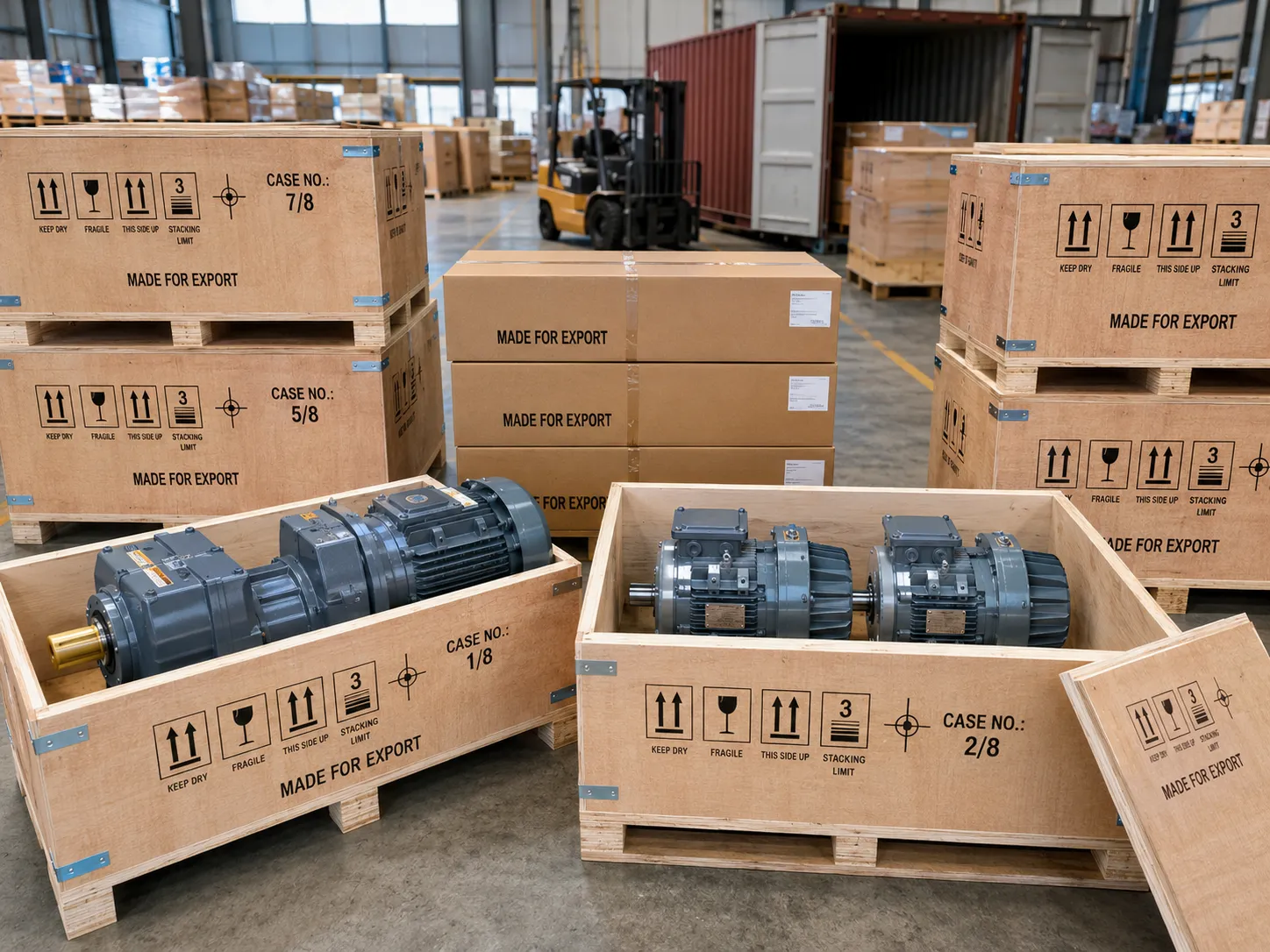
Before any mechanical work begins, inspect the motor carefully. Damage during transport is common and must be identified before installation, not after the motor has been wired into a control panel and connected to a driven machine.
Examine the frame, end shields, fan cover, terminal box, and shaft extension for cracks, dents, or impact damage. Check that the shaft rotates freely by hand with smooth resistance — any roughness, grinding, or hard spots indicate bearing damage from shock loading in transit. Check the nameplate is intact and legible.
Before connecting any supply cable, test the stator winding insulation resistance with a 500 V DC megohmmeter (for motors up to 1 kV rated voltage). Minimum acceptable reading is 1 MΩ at 20°C ambient. A motor stored in a humid environment may show lower values; if reading is below 1 MΩ, dry the motor in an oven at 80°C for 6 to 12 hours before proceeding.
Confirm the motor nameplate data matches the application requirements: power rating (kW), voltage (V), frequency (Hz), connection (star or delta), speed (rpm), frame size, IP rating, insulation class, and duty type. If any parameter does not match the specification, do not install the motor until the discrepancy is resolved with the supplier.
Check the shaft extension diameter and length against the coupling or sprocket bore dimensions. Verify the keyway dimensions (width and depth) match the key that will transmit torque to the driven component. Any burrs or raised edges on the shaft from transit contact must be removed with a fine file before fitting any power transmission element.
Step 2. Foundation and Baseplate Preparation
The motor foundation must be rigid enough to prevent vibration amplification during running, flat enough to avoid frame distortion when the hold-down bolts are tightened, and level to within the tolerance required for shaft alignment. A poorly prepared foundation is the most common cause of persistent vibration, premature bearing failure, and recurring alignment loss in industrial motor installations.
| Frame flatness tolerance | ≤ 0.1 mm over mounting footprint |
| Levelness | ≤ 0.05 mm/m in all directions |
| Foundation stiffness | Min. 3× motor + driven machine mass |
| Anchor bolt diameter | Per IEC 72-1 frame foot hole size |
| Grout (grouted bases) | Non-shrink epoxy grout |
For motors mounted on structural steel frames or machinery sub-frames (common for pump and fan sets), the baseplate must be checked for flatness with a precision straight-edge and feeler gauges before bolting the motor down. Any gap greater than 0.05 mm under the motor feet must be corrected with stainless steel shim packs, not by over-tightening the hold-down bolts, which will introduce frame distortion and stator bore ovality.
Soft foot warning: tightening hold-down bolts on an uneven base distorts the motor frame, slightly deforming the stator bore and reducing the air gap uniformity between stator and rotor. This causes increased vibration, noise, and in severe cases accelerates winding failure through stator-rotor contact. Always correct soft foot before final bolt torque.
Step 3. Mounting the Motor
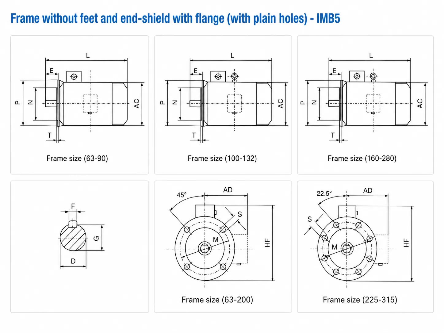
How the motor is mounted depends on whether it uses foot mounting (IMB3), flange mounting (IMB5), or the combined foot-and-flange arrangement (IMB35). The drive side (DE) bearing carries radial loads from belt, chain, or gear drives; the non-drive end (NDE) bearing is lightly loaded and carries mainly the rotor weight.
| Mounting Code | Description | Typical Application | Key Installation Note |
|---|---|---|---|
| IMB3 | Foot-mounted, shaft horizontal | Most pumps, fans, compressors, conveyors | Four-point foot contact; check all four feet for soft foot before final torque |
| IMB5 | Flange-mounted, shaft horizontal | Close-coupled pumps, gearboxes, direct machine mounting | Flange register (spigot) must be clean and undamaged; check concentricity with dial gauge |
| IMB35 | Foot and flange, shaft horizontal | Large geared pump sets, heavy machine tool drives | Flange carries alignment; feet provide stability only. Fit flange first, then shim feet to contact |
| IMV1 | Foot-mounted, shaft vertical downward | Vertical pump sets, mixer agitator drives | Confirm motor specified for vertical operation; NDE bearing must carry rotor weight axially |
| IMV3 | Flange-mounted, shaft vertical upward | Ceiling-mounted fans, overhead conveyors | Fan cover must face down for ventilation; confirm correct fan orientation before installation |
For belt-driven applications (the most common indirect drive arrangement for three-phase motors), the belt tension must be set correctly after alignment. Insufficient belt tension causes slip and belt overheating; excessive tension imposes radial overhang load on the drive-end bearing beyond the motor’s rated overhang capacity, dramatically shortening bearing service life. Consult the Korea Ever-Power bearing load capacity table for each frame size, available from the technical support team.
Step 4. Shaft Alignment
Shaft misalignment between the motor and driven machine is the leading cause of premature bearing failure, coupling wear, and excessive vibration in direct-coupled motor-drive trains. Even a well-commissioned motor will fail within a fraction of its expected bearing life if the shaft alignment is outside tolerance. Two types of misalignment must both be corrected:
The shaft centrelines are parallel but offset in the radial direction. Measured as the gap difference between coupling halves at top-bottom or left-right positions using a dial indicator rotated around the coupling. Maximum permissible parallel offset for flexible couplings: typically 0.05 to 0.10 mm for motor frame sizes up to 200, 0.10 to 0.15 mm for frame 250 and above.
The shaft centrelines intersect at an angle rather than being collinear. Measured as the face gap difference between the two coupling halves at diametrically opposite positions (top vs bottom, or left vs right). Maximum permissible angular misalignment: typically 0.05 mm per 100 mm coupling face diameter, equivalent to approximately 0.03°.
Lowest cost; suitable for preliminary rough alignment and belt-driven applications. Accuracy: ±0.1 mm typical. Not adequate for high-speed or high-precision direct couplings.
Standard industrial method. One or two dial gauges mounted on one coupling half, reading against the other. Accuracy: ±0.02 mm with care. Adequate for most motor installations up to 3,000 rpm.
Highest accuracy and fastest measurement. Laser emitter and receiver clamp to each shaft; digital readout gives real-time offset and angle values in both planes simultaneously. Accuracy: ±0.005 mm. Required for motors above 1,000 kW or above 3,000 rpm.
Step 5. Electrical Connection and Grounding
The terminal box of a three-phase induction motor contains six terminals: U1, V1, W1 (supply end of each phase winding) and U2, V2, W2 (other end of each phase winding). The connection arrangement determines whether the motor runs in star (Y) or delta (△) configuration, which determines the voltage the individual windings see and therefore the motor’s operating voltage.
Connect U2, V2, W2 together at the star point using the shorting links provided. Connect the three-phase supply to U1, V1, W1. In star connection, each winding sees the phase voltage (380 V ÷ √3 = 220 V). Star connection is used when the motor is rated 380 V/220 V and the supply is 380 V three-phase.
Connect U1-W2, V1-U2, W1-V2 using the shorting links in a triangular (delta) arrangement. Connect the three-phase supply to the three link junction points. In delta connection, each winding sees the full line voltage (220 V). Delta is used when the supply is 220 V three-phase or when the motor is rated 660 V/380 V on a 380 V supply.
Phase rotation check: after wiring, but before connecting the driven load, run the motor briefly and check the shaft rotation direction. If it runs backward (wrong direction), swap any two of the three supply phases at the terminal box. Never correct motor rotation direction by mechanical means on the driven machine side.
The motor frame must be connected to the protective earth (PE) conductor of the supply cable at the earth terminal in the terminal box. The PE conductor cross-section must be at minimum equal to the supply phase conductor cross-section for conductors up to 16 mm². Failure to earth the motor frame creates a dangerous shock hazard if an internal winding fault connects phase voltage to the frame.
Step 6. Pre-Start Checks and First Run
Repeat the megohmmeter test at 500 V DC between each phase and earth before energising. Reading must be above 1 MΩ. If any reading has fallen since the pre-installation test, investigate for moisture or wiring fault before proceeding.
Set the thermal overload relay or motor protection relay to the motor nameplate full-load current. Do not set it higher “to avoid nuisance trips” — the overload relay is the last line of defence against overheating if the motor is overloaded or loses a phase.
If possible, decouple the motor from the driven machine for the first run. This allows checking rotation direction, listening for bearing noise, and measuring no-load current (should be 30 to 60 percent of nameplate current) without risk to the driven equipment. Re-couple only after confirming correct direction and smooth running.
After coupling and loading, measure all three phase currents with a clamp meter. They should be within 5 percent of each other and below the nameplate full-load current at the operating load. After 30 minutes of running at full load, check the motor frame temperature — it should be warm but not too hot to touch (Class F motors: frame temperature up to 70°C above ambient is normal).
Measure vibration velocity at the bearing housings. IEC 60034-14 sets maximum vibration velocity at 2.8 mm/s RMS for standard-grade motors in frame 56 to 400. Levels above 4.5 mm/s indicate a problem — most commonly misalignment, unbalanced coupling, or resonance with the foundation structure.
Document the installation date, measured values (insulation resistance, current balance, vibration), alignment readings, coupling type and setting, overload relay setting, and initial bearing temperature. This baseline data is essential for condition monitoring comparison at future maintenance intervals.
IEC Mounting Method Reference
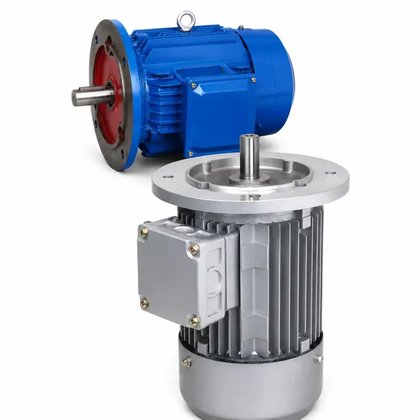
The full range of Korea Ever-Power Y2 series three-phase motors is available in all standard IEC mounting configurations. Terminal box position can be rotated to four positions to suit cable entry direction without changing the mounting arrangement. For detailed dimensional drawings and mounting bolt torque specifications for each frame size, consult the product pages or request dimensional data from the Korea Ever-Power engineering team.

Frequently Asked Questions
Edited by Cxm