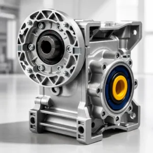
एफ सीरीज पैरेलल शाफ्ट हेलिकल गियर रिड्यूसर
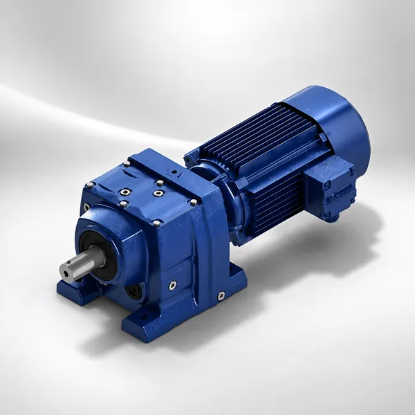
IEC B5 मोटर इनपुट फ्लेंज और ठोस या खोखले आउटपुट शाफ्ट के साथ समानांतर शाफ्ट हेलिकल गियर रिड्यूसर, F27 से F157 साइज़ में उपलब्ध है। मोटर और आउटपुट शाफ्ट समानांतर तलों में चलते हैं, जिससे F सीरीज़ कन्वेयर टेल-एंड ड्राइव, रोलर टेबल ड्राइव और किसी भी ऐसे अनुप्रयोग के लिए पसंदीदा विनिर्देश बन जाती है जहां मोटर को लोड शाफ्ट के पीछे एक ही अक्षीय रेखा में रखने के बजाय उसके बगल में स्थित होना आवश्यक है।
अनुपात: 3.77 – 289.74
आउटपुट टॉर्क: 120 – 15,000 एन·मी
समानांतर शाफ्ट आउटपुट
दक्षता: प्रति चरण 98% तक
आईपी55 सुरक्षा
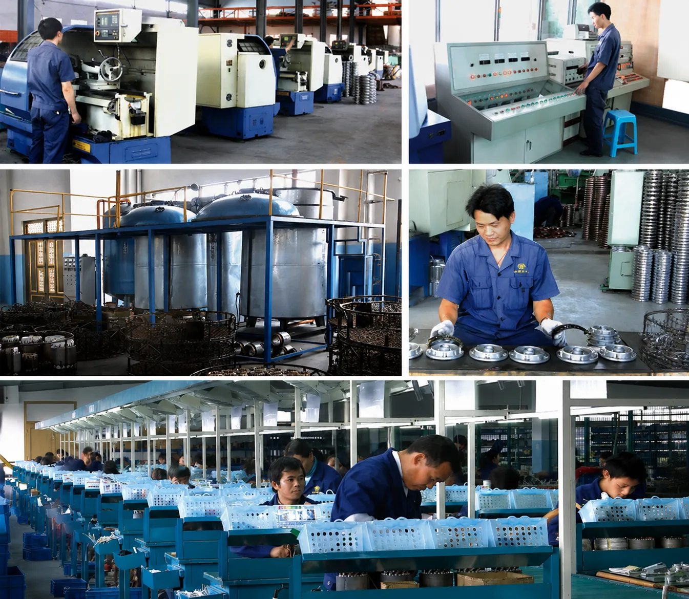
मोटर और लोड अगल-बगल: समानांतर शाफ्ट का लाभ
एफ सीरीज़ के पैरेलल शाफ्ट हेलिकल गियर रिड्यूसर में मोटर फ्लैंज गियरबॉक्स बॉडी के किनारे पर स्थित होता है, जिसमें आउटपुट शाफ्ट मोटर इनपुट शाफ्ट के समानांतर और उससे थोड़ा हटकर चलता है। यह ज्यामिति आर सीरीज़ के कोएक्सियल अरेंजमेंट से मौलिक रूप से भिन्न है: एफ सीरीज़ में, मोटर गियरबॉक्स के पीछे की बजाय उसके बगल में स्थित होता है, जिससे ड्राइव असेंबली की कुल अक्षीय लंबाई लगभग मोटर की लंबाई के बराबर कम हो जाती है। कन्वेयर ड्राइव, रोलर टेबल ड्राइव और पैकेजिंग मशीन ड्राइव में जहां लोड शाफ्ट के पीछे जगह सीमित होती है, वहां यह कॉम्पैक्ट अक्षीय आकार एक निर्णायक यांत्रिक लाभ प्रदान करता है।
एफ श्रृंखला में हेलिकल गियर चरण प्रति चरण 98% तक की दक्षता प्राप्त करते हैं, जो आर श्रृंखला के समान है, क्योंकि दोनों उत्पाद लाइनों में गियर दांतों की ज्यामिति और सामग्री विनिर्देश समान हैं: 20CrMnTi केस-कठोर मिश्र धातु इस्पात, जिसे ऊष्मा उपचार के बाद ISO 1328 ग्रेड 6 की सटीकता तक प्रोफाइल-ग्राउंड किया गया है। दो-चरणीय एफ श्रृंखला गियरबॉक्स लगभग 96% की समग्र दक्षता प्राप्त करता है; तीन-चरणीय इकाई लगभग 94% की दक्षता प्राप्त करती है। ये मान समानांतर शाफ्ट ज्यामिति की परवाह किए बिना स्थिर रहते हैं, क्योंकि गियर मेश विशेषताएँ इनपुट और आउटपुट शाफ्ट की सापेक्ष स्थिति से नहीं, बल्कि दांतों के आकार और सामग्री से निर्धारित होती हैं।
एफ37 और उससे ऊपर के मॉडलों में उपलब्ध हॉलो शाफ्ट (श्रिंक डिस्क) आउटपुट विकल्प, एफ सीरीज को बिना किसी अलग कपलिंग के रोलर, ड्रम या स्प्रोकेट के लोड शाफ्ट पर सीधे माउंट करने की अनुमति देता है, जिससे शाफ्ट अलाइनमेंट की आवश्यकता समाप्त हो जाती है और दिए गए अनुपात और आउटपुट टॉर्क के लिए ड्राइव असेंबली की लंबाई को न्यूनतम संभव स्तर तक कम किया जा सकता है।
यहां पर उपलब्ध उपयुक्त मोटर रेंज देखें तीन-चरण प्रेरण मोटरया फिर गियरबॉक्स की पूरी श्रृंखला को यहां ब्राउज़ करें हेलिकल गियर रिड्यूसर.
एफ सीरीज़ के आकार और प्रदर्शन संबंधी डेटा
1440 आरपीएम की निर्धारित इनपुट गति पर प्रदर्शन डेटा (4-पोल मोटर)। प्रत्येक आकार के लिए 2-चरण और 3-चरण कॉन्फ़िगरेशन उपलब्ध हैं। दिखाए गए आउटपुट टॉर्क मान प्रत्येक हाउसिंग आकार के लिए अधिकतम हैं।
| आकार | चरणों | अनुपात सीमा | अधिकतम आउटपुट टॉर्क (एन·मी) | दक्षता (%) | आईईसी मोटर फ्रेम | अधिकतम इनपुट किलोवाट | वजन (किलोग्राम) |
|---|---|---|---|---|---|---|---|
| एफ27 | 2 | 3.77 – 24.35 | 120 | 96 | 71, 80, 90 | 1.5 | 5.0 |
| एफ37 | 2 | 3.77 – 24.35 | 200 | 96 | 80, 90, 100 | 2.2 | 8.5 |
| एफ47 | 2 / 3 | 3.77 – 289.74 | 350 | 94 – 96 | 90, 100, 112 | 4.0 | 14.0 |
| एफ57 | 2 / 3 | 3.77 – 289.74 | 550 | 94 – 96 | 100, 112, 132 | 5.5 | 21.0 |
| एफ67 | 2 / 3 | 3.77 – 289.74 | 900 | 94 – 96 | 112, 132, 160 | 9.2 | 30.0 |
| एफ77 | 2 / 3 | 5.21 – 289.74 | 1,500 | 94 – 96 | 132, 160, 180 | 15 | 50.0 |
| एफ87 | 2 / 3 | 5.21 – 289.74 | 2,400 | 94 – 96 | 160, 180, 200 | 30 | 72.0 |
| एफ97 | 2 / 3 | 5.21 – 289.74 | 3,800 | 94 – 96 | 180, 200, 225 | 45 | 105.0 |
| एफ107 | 2 / 3 | 5.21 – 289.74 | 6,000 | 94 – 96 | 200, 225, 250 | 75 | 155.0 |
| एफ127 | 2 / 3 | 5.21 – 289.74 | 9,000 | 94 – 96 | 225, 250, 280 | 110 | 230.0 |
| एफ157 | 2 / 3 | 5.21 – 289.74 | 15,000 | 94 – 96 | 250, 280, 315 | 160 | 360.0 |
गियरबॉक्स विनिर्देश
| गियर सामग्री | 20CrMnTi केस-कठोर |
| दांतों की सटीकता | आईएसओ 1328 ग्रेड 6 |
| आवास सामग्री | जीजेएल-250 कच्चा लोहा |
| गियर तेल | आईएसओ वीजी 220 सिंथेटिक |
| सुरक्षा | आईपी55 |
| तापीय सीमा | 100 डिग्री सेल्सियस तेल का तापमान |
| पेंट फ़िनिश | RAL 5010 नीला एपॉक्सी |
| बढ़ते | किसी भी अभिविन्यास |
इनपुट और आउटपुट कॉन्फ़िगरेशन
| इनपुट प्रकार | आईईसी बी5 फ्लैंज डायरेक्ट |
| शाफ्ट व्यवस्था | समानांतर ऑफसेट |
| आउटपुट शॉफ़्ट | ठोस कुंजी वाला (मानक) |
| खोखली शाफ़्ट | श्रिंक डिस्क (F37 से ऊपर) |
| आउटपुट फ्लेंज | F47 और उससे ऊपर के संस्करणों में उपलब्ध है |
| टोर्क आर्म | खोखले शाफ्ट के साथ शामिल है |
| आईईसी फ्रेम रेंज | 71 – 315 |
| मानकों | आईएसओ 9001 / सीई |
एफ सीरीज पैरेलल शाफ्ट हेलिकल रिड्यूसर के विशिष्ट अनुप्रयोग
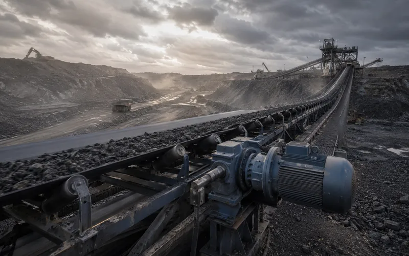
रोलर टेबल ड्राइव
स्टील मिल और रोलिंग मिल के रोलर टेबल में एफ सीरीज़ के पैरेलल शाफ्ट रिड्यूसर का उपयोग किया जाता है, जिसमें खोखले शाफ्ट आउटपुट को सीधे प्रत्येक रोलर शाफ्ट पर लगाया जाता है। पैरेलल ऑफसेट ज्यामिति मोटर को रोलर के पीछे के बजाय उसके बगल में रखती है, जिससे यह हॉट और कोल्ड रोलिंग लाइनों के संकीर्ण सेंटर-टू-सेंटर रोलर स्पेसिंग में आसानी से फिट हो जाती है और आस-पास की ड्राइव इकाइयों के बीच कोई रुकावट नहीं आती।
|
संचय कन्वेयर
वेयरहाउस सॉर्टेशन सिस्टम और वितरण केंद्रों में उपयोग होने वाले लाइव रोलर एक्यूमुलेशन कन्वेयर में प्रत्येक संचालित रोलर ज़ोन पर खोखले शाफ्ट आउटपुट वाले एफ सीरीज़ रिड्यूसर का उपयोग किया जाता है। कॉम्पैक्ट समानांतर शाफ्ट व्यवस्था ड्राइव यूनिट को कन्वेयर फ्रेम की चौड़ाई के भीतर रखती है और प्रत्येक रोलर ज़ोन में संचित ड्राइव मोटर और गियरबॉक्स असेंबली द्वारा घेरे गए स्थान को न्यूनतम करती है।
|

भारी औद्योगिक मिक्सर
बड़े औद्योगिक टैंकों पर लगे टॉप-एंट्री एजिटेटर, जहाँ वेसल नोजल के ऊपर उपलब्ध हेडस्पेस सीमित होता है, वहाँ F सीरीज़ रिड्यूसर का उपयोग किया जाता है। समानांतर शाफ्ट ज्यामिति, समाक्षीय इनलाइन व्यवस्था की तुलना में मोटर-गियरबॉक्स असेंबली की ऊर्ध्वाधर ऊँचाई को कम करती है, क्योंकि मोटर फ्लैंज गियरबॉक्स के ऊपर ऊर्ध्वाधर स्टैक ऊँचाई में वृद्धि करने के बजाय बग़ल में ऑफसेट होता है।
|
|
🔥
ड्रम और पुली ड्राइव
थोक सामग्री प्रबंधन संयंत्रों में कन्वेयर हेड पुली और टेल पुली ड्राइव में एफ सीरीज के खोखले शाफ्ट रिड्यूसर का उपयोग किया जाता है, जो सीधे पुली शाफ्ट स्टब एंड पर लगे होते हैं। इससे अलग कपलिंग और पिलो ब्लॉक बेयरिंग व्यवस्था की आवश्यकता समाप्त हो जाती है, जो अन्यथा आउटबोर्ड पुली बेयरिंग के साथ सॉलिड शाफ्ट रिड्यूसर का उपयोग करते समय आवश्यक होती।
|
🎏
पैकेजिंग मशीन ड्राइव
कार्टनिंग, रैपिंग और पैलेटाइजिंग मशीनों में मुख्य इनफीड और डिस्चार्ज कन्वेयर ड्राइव के लिए एफ सीरीज रिड्यूसर का उपयोग किया जाता है, जहां कॉम्पैक्ट पैरेलल शाफ्ट पैकेज मोटर और गियरबॉक्स को मशीन फ्रेम के भीतर माउंट करने की अनुमति देता है, जिससे मोटर मशीन के फुटप्रिंट से बाहर नहीं निकलती है।
|
⚙
पंप और पंखे के समानांतर ड्राइव
पंप स्किड व्यवस्थाओं में जहां दो पंपों को समानांतर ऑफसेट गियरबॉक्स के माध्यम से एक ही मोटर से संचालित किया जाना आवश्यक होता है, वहां एफ सीरीज रिड्यूसर का उपयोग किया जाता है। समानांतर शाफ्ट व्यवस्था मोटर के केंद्र की ऊंचाई को पंप शाफ्ट के केंद्र की ऊंचाई से मिलाने की अनुमति देती है, बिना किसी एडेप्टर प्लेट के, जिससे स्किड बेस का निर्माण और पाइपवर्क संरेखण सरल हो जाता है।
|
एफ सीरीज़ बनाम आर सीरीज़: पैरेलल और इनलाइन शाफ्ट में से चयन करना
अक्षीय लंबाई बनाम पार्श्व चौड़ाई
आर सीरीज़ (इनलाइन) की पार्श्व चौड़ाई सबसे कम होती है, लेकिन अक्षीय लंबाई सबसे अधिक होती है, क्योंकि मोटर गियरबॉक्स के पीछे लगी होती है और अक्षीय दिशा में मोटर और गियरबॉक्स दोनों की लंबाई जुड़ जाती है। एफ सीरीज़ (पैरेलल शाफ्ट) की पार्श्व चौड़ाई अधिक होती है क्योंकि मोटर का फ्लैंज गियरबॉक्स बॉडी के किनारे पर होता है, लेकिन कुल अक्षीय लंबाई केवल गियरबॉक्स की लंबाई होती है, क्योंकि मोटर अक्षीय प्रक्षेपण में कोई वृद्धि नहीं करती है। कन्वेयर ड्राइव में जहां हेड पुली के पीछे अक्षीय स्थान सीमित होता है (दीवार पर लगे ड्राइव, बंद टनल कन्वेयर पर टेल-एंड ड्राइव), वहां आर सीरीज़ के साथ दक्षता समतुल्यता की परवाह किए बिना एफ सीरीज़ मानक विकल्प है।
संचालित उपकरणों पर खोखला शाफ्ट
आर और एफ दोनों सीरीज श्रिंक डिस्क के माध्यम से खोखले शाफ्ट आउटपुट प्रदान करती हैं। व्यावहारिक अंतर यह है कि आर सीरीज का खोखला शाफ्ट मोटर के साथ समाक्षीय होता है, इसलिए मोटर को संचालित शाफ्ट के सिरे पर इस प्रकार लगाया जाना चाहिए कि मोटर के भार को संभालने के लिए एक टॉर्क आर्म का उपयोग किया जा सके। एफ सीरीज के खोखले शाफ्ट में मोटर एक तरफ ऑफसेट होती है, जिसका अर्थ है कि मोटर का भार आंशिक रूप से गियरबॉक्स बॉडी और आंशिक रूप से टॉर्क आर्म द्वारा वहन किया जाता है, जिससे समाक्षीय व्यवस्था की तुलना में संचालित शाफ्ट पर बेंडिंग मोमेंट कम हो जाता है। उन अनुप्रयोगों के लिए जहां संचालित शाफ्ट लंबा और पतला होता है (स्क्रू कन्वेयर, एजिटेटर शाफ्ट), एफ सीरीज का खोखला शाफ्ट गियरबॉक्स माउंटिंग बिंदु पर शाफ्ट का विक्षेपण कम करता है।
केंद्र ऊंचाई मिलान
एफ सीरीज़ की समानांतर शाफ्ट व्यवस्था, उपयुक्त गियरबॉक्स आकार और मोटर फ्रेम संयोजन का चयन करके आउटपुट शाफ्ट की केंद्र ऊंचाई को मानक आईईसी मोटर शाफ्ट केंद्र ऊंचाई या मानक पंप शाफ्ट केंद्र ऊंचाई से मेल खाने की अनुमति देती है। यह विशेष रूप से उन रेट्रोफिट स्थितियों में उपयोगी है जहां मौजूदा मोटर और गियरबॉक्स को मशीन के आधार या नींव में कोई बदलाव किए बिना, मौजूदा इंस्टॉलेशन की शाफ्ट केंद्र ऊंचाई से मेल खाने वाली मोटर-गियरबॉक्स इकाई से बदलना आवश्यक है। कोरिया एवर-पावर, ऑर्डर देने से पहले आयामी अनुकूलता की पुष्टि करने के लिए किसी भी एफ सीरीज़ आकार और मोटर फ्रेम संयोजन के लिए केंद्र ऊंचाई आयाम चित्र प्रदान कर सकता है।

एफ सीरीज पैरेलल शाफ्ट हेलिकल रिड्यूसर से संबंधित अक्सर पूछे जाने वाले प्रश्न
एफ सीरीज पैरेलल शाफ्ट हेलिकल रिड्यूसर के लिए कोटेशन का अनुरोध करें
आकार, अनुपात, मोटर की स्थिति (बाएँ या दाएँ), आउटपुट शाफ्ट का प्रकार, माउंटिंग ओरिएंटेशन और मोटर फ्रेम निर्दिष्ट करें। हमारी फैक्ट्री के बारे में अधिक जानने के लिए यहाँ क्लिक करें। हमारे बारे में पृष्ठ।
Cxm द्वारा संपादित
अतिरिक्त जानकारी
| संपादक | सीएक्सएम |
|---|