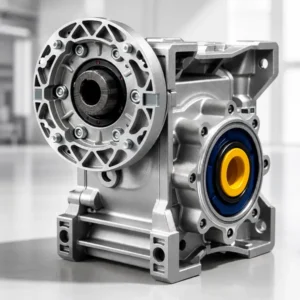
Špirálový redukčný prevod s paralelným hriadeľom série F
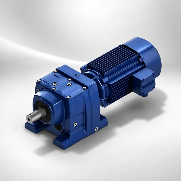
Špirálový redukčný prevod s paralelným hriadeľom, vstupnou prírubou motora IEC B5 a plným alebo dutým výstupným hriadeľom, dostupný vo veľkostiach F27 až F157. Motor a výstupný hriadeľ prebiehajú v rovnobežných rovinách, vďaka čomu je séria F preferovanou špecifikáciou pre pohony zadných častí dopravníkov, pohony valčekových stolov a akékoľvek aplikácie, kde musí byť motor umiestnený vedľa hriadeľa záťaže a nie za ním v rovnakej axiálnej línii.
Pomery: 3,77 – 289,74
Výstupný krútiaci moment: 120 – 15 000 N·m
Výstup s paralelným hriadeľom
Účinnosť: až 981 TP3T na stupeň
Krytie IP55
Motor a záťaž vedľa seba: Výhoda paralelných hriadeľov
Špirálový redukčný prevod s paralelným hriadeľom série F umiestňuje prírubu motora na boku telesa prevodovky, pričom výstupný hriadeľ prebieha rovnobežne so vstupným hriadeľom motora a je od neho odsadený. Táto geometria sa zásadne líši od koaxiálneho usporiadania série R: v sérii F je motor umiestnený vedľa prevodovky a nie za ňou, čo znižuje celkovú axiálnu dĺžku zostavy pohonu približne o dĺžku motora. Pre pohony dopravníkov, pohony valčekových stolov a pohony baliacich strojov, kde je priestor za hriadeľom záťaže obmedzený, je tento kompaktný axiálny obal rozhodujúcou mechanickou výhodou.
Špirálové prevodovky série F dosahujú účinnosť až 981 TP3T na stupeň, čo je identické s radom R, pretože obe produktové rady majú rovnakú geometriu zubov ozubeného kolesa a materiálové špecifikácie: kalená legovaná oceľ 20CrMnTi, profilovo brúsená na presnosť ISO 1328 triedy 6 po tepelnom spracovaní. Dvojstupňová prevodovka série F dosahuje celkovú účinnosť približne 961 TP3T; trojstupňová jednotka približne 941 TP3T. Tieto hodnoty sú konzistentné bez ohľadu na geometriu rovnobežných hriadeľov, pretože charakteristiky záberu ozubených kolies sú určené tvarom a materiálom zubov, nie relatívnou polohou vstupného a výstupného hriadeľa.
Možnosť výstupu s dutým hriadeľom (sťahovacím kotúčom), dostupná od modelu F37 a vyššieho, umožňuje montáž série F priamo na hriadeľ záťaže valca, bubna alebo ozubeného kolesa bez samostatnej spojky, čím sa eliminujú požiadavky na zarovnanie hriadeľa a ďalej sa skracuje dĺžka zostavy pohonu na minimum pre daný prevodový pomer a výstupný krútiaci moment.
Preskúmajte sortiment zodpovedajúcich motorov na Trojfázové indukčné motoryalebo si prezrite kompletný rad prevodoviek na Špirálové reduktory.
Údaje o veľkosti a výkone série F
Údaje o výkone pri menovitých vstupných otáčkach 1440 ot./min. (4-pólový motor). K dispozícii sú 2-stupňové a 3-stupňové konfigurácie podľa veľkosti. Uvedené hodnoty výstupného krútiaceho momentu sú maximálne pre každú veľkosť krytu.
| Veľkosť | Etapy | Rozsah pomeru | Maximálny výstupný krútiaci moment (N·m) | Účinnosť (%) | Rámy motorov IEC | Maximálny príkon kW | Hmotnosť (kg) |
|---|---|---|---|---|---|---|---|
| F27 | 2 | 3,77 – 24,35 | 120 | 96 | 71, 80, 90 | 1.5 | 5.0 |
| F37 | 2 | 3,77 – 24,35 | 200 | 96 | 80, 90, 100 | 2.2 | 8.5 |
| F47 | 2 / 3 | 3,77 – 289,74 | 350 | 94 – 96 | 90, 100, 112 | 4.0 | 14.0 |
| F57 | 2 / 3 | 3,77 – 289,74 | 550 | 94 – 96 | 100, 112, 132 | 5.5 | 21.0 |
| F67 | 2 / 3 | 3,77 – 289,74 | 900 | 94 – 96 | 112, 132, 160 | 9.2 | 30.0 |
| F77 | 2 / 3 | 5,21 – 289,74 | 1,500 | 94 – 96 | 132, 160, 180 | 15 | 50.0 |
| F87 | 2 / 3 | 5,21 – 289,74 | 2,400 | 94 – 96 | 160, 180, 200 | 30 | 72.0 |
| F97 | 2 / 3 | 5,21 – 289,74 | 3,800 | 94 – 96 | 180, 200, 225 | 45 | 105.0 |
| F107 | 2 / 3 | 5,21 – 289,74 | 6,000 | 94 – 96 | 200, 225, 250 | 75 | 155.0 |
| F127 | 2 / 3 | 5,21 – 289,74 | 9,000 | 94 – 96 | 225, 250, 280 | 110 | 230.0 |
| F157 | 2 / 3 | 5,21 – 289,74 | 15,000 | 94 – 96 | 250, 280, 315 | 160 | 360.0 |
Špecifikácie prevodovky
| Materiál ozubeného kolesa | 20CrMnTi cementované |
| Presnosť zubov | ISO 1328 Trieda 6 |
| Materiál krytu | Liatina GJL-250 |
| Prevodový olej | Syntetický olej ISO VG 220 |
| Ochrana | IP55 |
| Tepelný limit | teplota oleja 100 °C |
| Povrchová úprava náterom | RAL 5010 modrý epoxid |
| Montáž | Akákoľvek orientácia |
Konfigurácie vstupov a výstupov
| Typ vstupu | Priama príruba IEC B5 |
| Usporiadanie hriadeľa | Paralelné odsadenie |
| Výstupný hriadeľ | S plným kľúčom (štandard) |
| Dutý hriadeľ | Zmršťovací kotúč (od F37) |
| Výstupná príruba | K dispozícii F47 a vyššie |
| Momentová páka | Súčasťou balenia je dutý hriadeľ |
| Rozsah rámov IEC | 71 – 315 |
| Normy | ISO 9001 / CE |
Typické aplikácie pre redukčné systémy s paralelným hriadeľom série F

Pohony valčekových stolov
Valčekové stoly oceliarní a valcovní používajú reduktory s paralelným hriadeľom série F s dutým hriadeľom namontovaným priamo na každom hriadeli valca. Paralelná odsadená geometria umiestňuje motor vedľa valca a nie zaň, čím sa zapadá do úzkej vzdialenosti medzi stredmi valcov liniek valcovania za tepla a za studena bez prekážok medzi susednými pohonnými jednotkami.
|

Akumulačné dopravníky
Valčekové dopravníky s aktívnym pohonom v triediacich systémoch skladov a distribučných centrách používajú reduktory série F s dutým hriadeľom na výstupe v každej poháňanej valčekovej zóne. Kompaktné usporiadanie paralelných hriadeľov udržiava pohonnú jednotku v šírke rámu dopravníka a minimalizuje podlahovú plochu, ktorú zaberá akumulovaný hnací motor a prevodovka na valčekovú zónu.
|

Ťažké priemyselné miešačky
Miešadlá s horným vstupom na veľkých priemyselných nádržiach, kde je k dispozícii obmedzený priestor nad tryskou nádoby, používajú reduktory série F. Geometria rovnobežného hriadeľa znižuje vertikálnu výšku zostavy motora a prevodovky v porovnaní s koaxiálnym radovým usporiadaním, pretože príruba motora je posunutá do strán, a nie je pridaná k vertikálnej výške stohu nad prevodovkou.
|
|
🔥
Pohony bubnov a kladiek
Pohony kladiek hornej a zadnej kladky dopravníka v zariadeniach na manipuláciu s sypkým materiálom používajú reduktory s dutým hriadeľom série F namontované priamo na konci hriadeľa kladky, čím sa eliminuje samostatná spojka a usporiadanie ložiska stojanu, ktoré by inak bolo potrebné pri použití reduktora s plným hriadeľom s vonkajším ložiskom kladky.
|
🎏
Pohony baliacich strojov
Kartónovacie, baliace a paletizačné stroje používajú reduktory série F pre pohony hlavného vstupného a výstupného dopravníka, kde kompaktný balík s paralelnými hriadeľmi umožňuje montáž motora a prevodovky v ráme stroja bez toho, aby motor vyčnieval za pôdorys stroja.
|
⚙
Paralelné pohony čerpadiel a ventilátorov
Usporiadania s lyžinami čerpadla, kde musia byť dve čerpadlá poháňané z jedného motora cez paralelnú odsadenú prevodovku, používajú reduktory série F. Usporiadanie s paralelným hriadeľom umožňuje, aby výška stredu motora zodpovedala výške stredu hriadeľa čerpadla bez adaptérovej dosky, čo zjednodušuje výrobu základne lyžín a zarovnanie potrubia.
|
Séria F vs. séria R: Výber medzi paralelným a radovým hriadeľom
Axiálna dĺžka vs. priečna šírka
Séria R (radová) má najkratšiu priečnu šírku, ale najdlhšiu axiálnu dĺžku, pretože motor je umiestnený za prevodovkou a dĺžky motora aj prevodovky sa v axiálnom smere sčítavajú. Séria F (paralelný hriadeľ) má väčšiu priečnu šírku, pretože príruba motora je na boku telesa prevodovky, ale celková axiálna dĺžka je iba dĺžka prevodovky, pretože motor nepridáva k axiálnemu presahu. Pre pohony dopravníkov, kde je axiálny priestor za hlavnou kladkou obmedzený (nástenné pohony, pohony zadnej časti na uzavretých tunelových dopravníkoch), je séria F štandardnou voľbou bez ohľadu na účinnosť porovnateľnú so sériou R.
Dutý hriadeľ na poháňanom zariadení
Série R aj F ponúkajú výstup dutého hriadeľa cez zmršťovací kotúč. Praktický rozdiel spočíva v tom, že dutý hriadeľ série R je súosový s motorom, takže motor musí byť umiestnený na konci hnaného hriadeľa s momentovou pákou reagujúcou na hmotnosť motora. Dutý hriadeľ série F má motor odsadený do strany, čo znamená, že hmotnosť motora je čiastočne podopretá telesom prevodovky a čiastočne momentovou pákou, čím sa znižuje ohybový moment na hnanom hriadeli v porovnaní s koaxiálnym usporiadaním. Pre aplikácie, kde je hnaný hriadeľ dlhý a štíhly (závitovkové dopravníky, hriadele miešadiel), dutý hriadeľ série F vytvára menšie vychýlenie hriadeľa v bode upevnenia prevodovky.
Zladenie výšky stredu
Paralelné usporiadanie hriadeľov série F umožňuje prispôsobiť výšku stredu výstupného hriadeľa štandardným výškam stredu hriadeľa motora IEC alebo štandardným výškam stredu hriadeľa čerpadla výberom vhodnej kombinácie veľkosti prevodovky a rámu motora. Toto je obzvlášť užitočné v situáciách dodatočnej montáže, kde je potrebné existujúci motor a prevodovku vymeniť za jednotku motora a prevodovky, ktorá zodpovedá výške stredu hriadeľa existujúcej inštalácie bez úpravy základne alebo základu stroja. Spoločnosť Korea Ever-Power môže poskytnúť rozmerové výkresy výšky stredu pre akúkoľvek kombináciu veľkosti série F a rámu motora, aby sa pred objednaním overila rozmerová kompatibilita.

Často kladené otázky – Špirálový reduktor s paralelným hriadeľom série F
Vyžiadajte si cenovú ponuku na redukcie s paralelným hriadeľom série F
Uveďte veľkosť, prevodový pomer, polohu motora (vľavo alebo vpravo), typ výstupného hriadeľa, orientáciu montáže a rám motora. Získajte informácie o našej továrni na O nás stránka.
Upravil Cxm
Ďalšie informácie
| Redaktor | Cxm |
|---|